Iveco Daily Euro 4. Manual - part 115


  Index      Iveco     Iveco Daily Euro 4 - service repair manual 2006 year


Search            


Content   ..  113  114  115  116   ..


Iveco Daily Euro 4. Manual - part 115


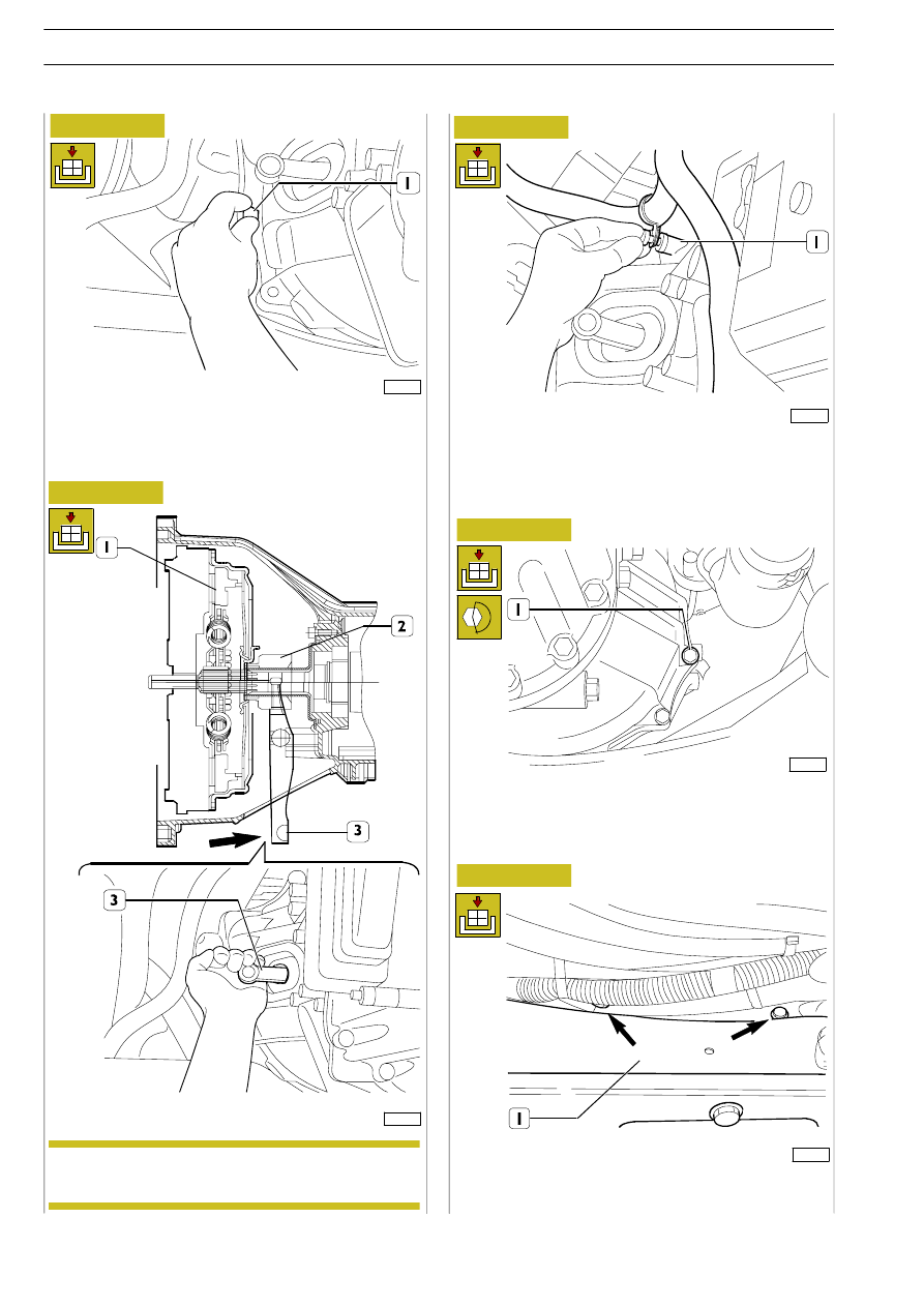
Secure the cable to the gearbox by means of the special
fasteners (1).

Screw down gearbox fastening screws (1) by tightening them
to torque.

Screw down screws (1), then fit the engine lower cover.

102158

102160

102159

102161

102145

Figure 43

Figure 44

Figure 45

Figure 46

Figure 47

Manually screw down screws (1) securing the gearbox case to
the base unit prior to tightening them to torque.

Pull the fork (3) towards the control unit, so that
pressure plate bearing (2) is correctly engaged into
diaphragm spring (1).

NOTE

114

6 S 400 A O.D. TRANSMISSION

D

AILY

E

URO

4

Secure crossbar (1) to the gearbox and to the chassis by
tightening the screws to the specified torque.

Fit the clutch actuator (1) engaging tip into the special fork slot,
taking care not to touch it straight with your hands.

Secure clutch actuator (1) to the gearbox by means of the four
screws (2), then tighten to the specified torque.

Connect connector (1) to the clutch actuator.

Secure the gearbox cable by means of strap (1).

102163

102141

102149

102165

102167

102168

Figure 48

Figure 49

Figure 50

Figure 51

Re-attach the starting motor to the gearbox case front cover
by tightening the screws (1) to the specified torque.

Figure 52

Figure 53

6 S 400 A O.D. TRANSMISSION

115

D

AILY

E

URO

4

Properly secure the connector until the pull-back spring clicks
into position (see arrow).

Connect the reverse light (1) and revs number sensor (2)
connectors.

Connect the electrical connections of the power take-off, if
present, from the other side of gearbox.

Secure the wiring to the gearbox, as shown by the arrows in
the figure.

102169

102172

102170

102171

102143

Figure 54

Figure 55

Figure 56

Figure 57

Connect connectors (1) to the control unit.

Secure drive shaft (1) to the gearbox by tightening fastening
screws (2) to torque.

After the gearbox has been re-attached completely, check for
correct connection of electric cables.

Figure 58

After re-attachment has been completed, perform
the specific calibration procedure by means of the
diagnosis instrument described on page 122/30.

NOTE

116

6 S 400 A O.D. TRANSMISSION

D

AILY

E

URO

4

102162

Place the vehicle in a pit or on an auto lift.
Disconnect the battery cable in the engine compartment.

As far as gearbox unit overhauling is concerned,
follow the instructions and illustrations relative to
the 6 S 400 O.D. gearbox unit.
Below are the descriptions and illustrations relative
to

the

replacement

of

the

gearbox

unit

electric/electronic components supplied with spare
parts.

66136114 CONTROL UNIT

Removal

Remove connector (4) from control unit (1) by pulling the safety retainer downwards, as shown by the arrow.
Remove strap (6). Unscrew screws (2, 3).
Remove screw (5) while holding the control unit and taking care to recover spacer (7) placed behind screw (3). Take off control
unit (1).

Figure 59

NOTE

6 S 400 A O.D. TRANSMISSION

117

D

AILY

E

URO

4


Content   ..  113  114  115  116   ..