Iveco Daily Euro 4. Manual - part 113
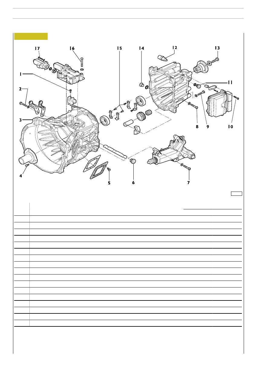
Figure 16
101948
: Spread LOCTITE 5206 sealant on the contact surfaces
F Spread LOCTITE 242 on the thread
J Spread LOCTITE 510 on the thread
106
6 S 400 A O.D. TRANSMISSION
D
AILY
E
URO
4
DESCRIPTION
TORQUE
DESCRIPTION
Nm
kgm
1D
Screw securing driver to main rod
9.5
0.9
2
Gearbox actuator support fastening screw
23
2.3
3
Clutch housing, screw to fasten clutch housing to crankcase
80
8
4
Constant mesh shaft cover fastening screw
23
±15%
2.3
±15%
5
J
Screw securing p.t.o. side cover
46
±15%
4.6
±15%
6
Plugs for rod preventing gear engagement
32
3.2
7
Clutch actuator fastening screws
23
2.3
8
Screw securing reverse gear shaft
23
±15%
2.3
±15%
9*
Screw securing rear cover
23
±15%
2.3
±15%
10
Electronic control unit fastening screws
9.5
0.9
11
Side plug on rear cover
35
3.5
12
Speedometer transmitter fixing
50
5
13
Screw locking sleeve for transmission coupling on main shaft
235
23.5
14
Cap
32
3.2
15D
Screw securing ball bearing retaining ring
9.5
±15%
0,.
±15%
16
Gearbox actuator fastening screws
23
3.2
17
Electric motor fastening screws
-
-