Iveco Daily Euro 4. Manual - part 107
51974
90221
51975
90222
90223
51973
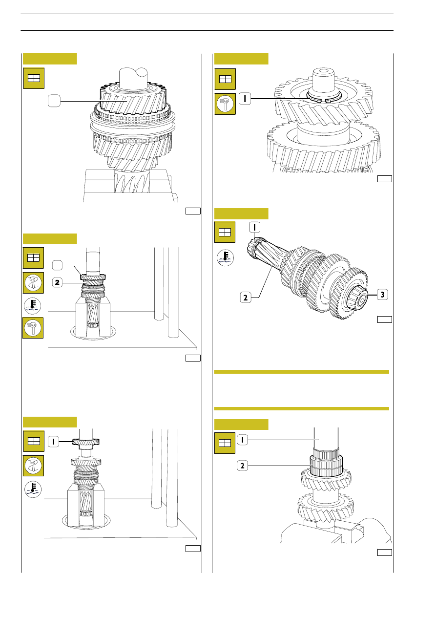
Figure 94
Figure 95
Figure 96
Figure 97
Figure 98
Figure 99
Mount the 3rd gear (1).
With a hydraulic press, mount the 6
th
gear (1) pre-heated to
approx. 170
°C.
Check the end float of the 3
rd
gear (2). It should be 0.15
÷0.40
mm.
With a hydraulic press, mount the 5
th
gear (1) pre-heated to
approx. 170
°C.
Mount the retaining ring (1) whose thickness produces null
end float in its seat.
Heat the internal rings (1-3) of the tapered roller bearings to
a temperature of approx. 80
°C and, with a suitable punch (1),
mount them on the transmission shaft (2).
Tighten the main shaft (1) and position the roller bearing (2)
on it.
Mounting the main shaft
Mount the synchronizer rings on their respective gears
according to the marks made during disassembly or
when checking in the case of replacement.
1
1
NOTE
82
6 S 400 O.D. TRANSMISSION
D
AILY
E
URO
4