Engines Iveco C10,C13, Cursor 10, Cursor 13. Manual - part 56
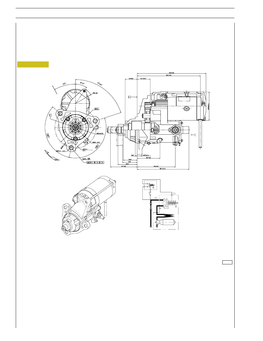
Figure 27
Starting motor
Specifications
Supplier
DENSO
Type
2280007550
Electrical system
24 Volt
Nominal output
5.5 Kw
104315
50
SECTION 3 - INDUSTRIAL APPLICATION
F3B CURSOR ENGINES
Base - May 2007