Engines Iveco C10,C13, Cursor 10, Cursor 13. Manual - part 30
60593
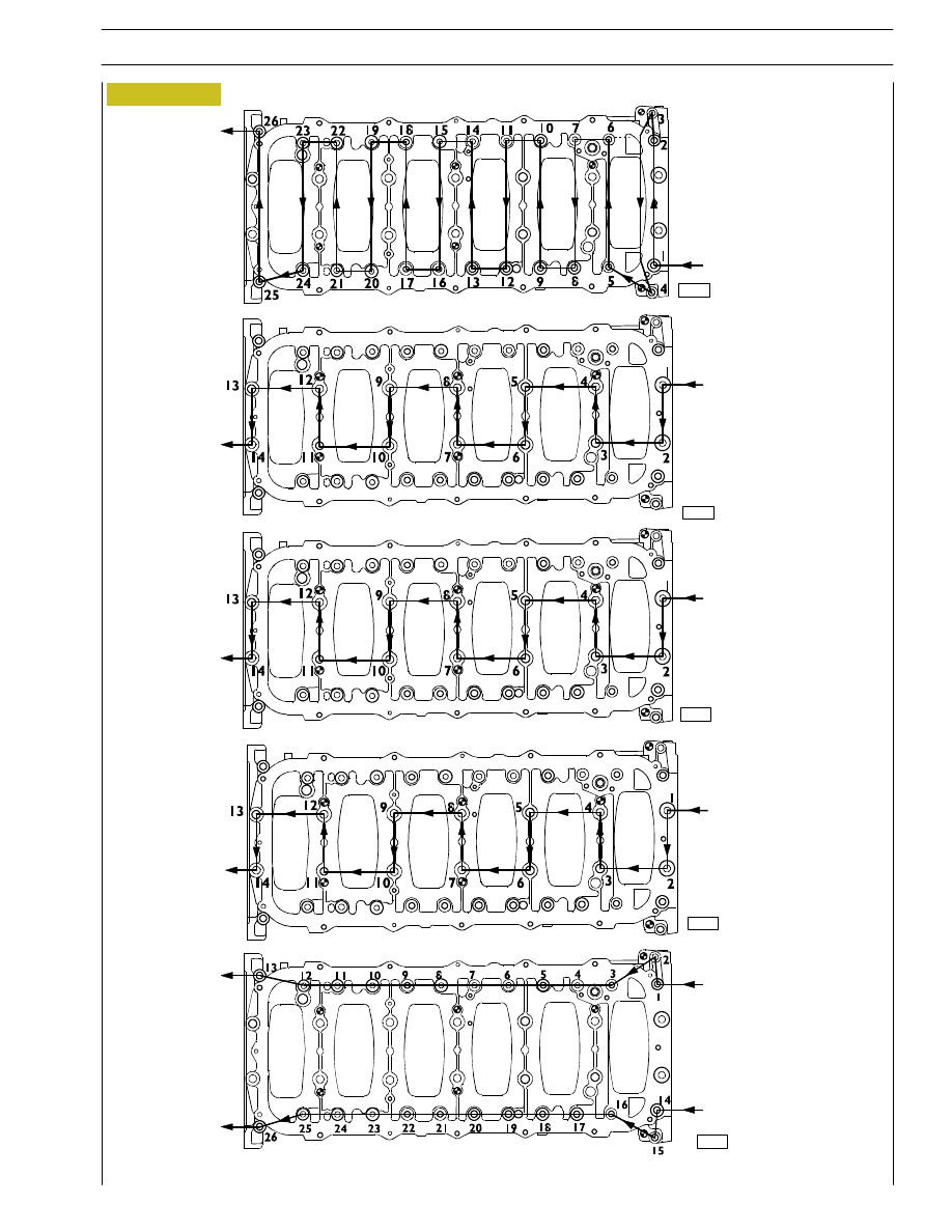
FRONT SIDE
stage 4:
angle
inner
screws
(45º)
60592
60594
Figure 47
stage 1:
pretightening
outer screws
(30 Nm)
FRONT SIDE
FRONT SIDE
FRONT SIDE
stage 2:
pretightenig
inner screws
(120 Nm)
stage 5:
angle
outer
screws
(60º)
FRONT SIDE
stage 3:
angle
inner
screws
(90º)
60593
60593
DIAGRAM OF TIGHTENING SEQUENCE OF CRANKCASE BASE FIXING SCREWS
27
CURSOR ENGINES F3A
SECTION 4 - OVERHAUL AND TECHNICAL SPECIFICATIONS
Base - May 2007