Engines Iveco C10,C13, Cursor 10, Cursor 13. Manual - part 14
20
SECTION 3 - INDUSTRIAL APPLICATION
CURSOR ENGINES F3A
Base - May 2007
60573
60575
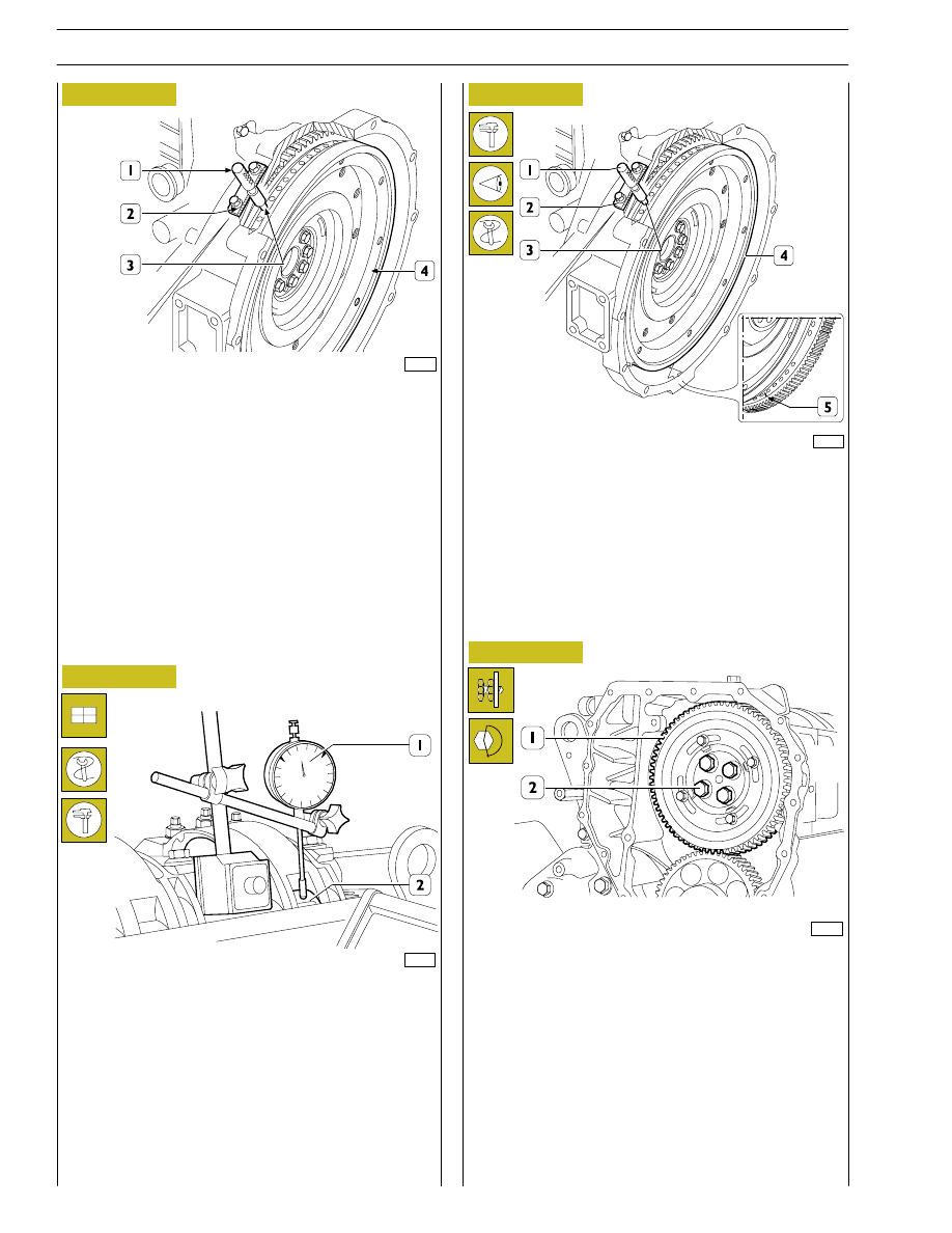
Figure 61
Figure 62
Figure 63
Figure 64
The exact position of piston no.1 at the T.D.C. is obtained
when in the above-described conditions the tool 99360612
(1) goes through the seat (2) of the engine speed sensor into
the hole (3) in the engine flywheel (4).
If this is not the case, turn and adjust the engine flywheel (4)
appropriately.
Remove the tool 99360612 (1).
Set the dial gauge with the magnetic base (1) with the rod on
the roller (2) of the rocker arm that governs the injector of
cylinder no.1 and pre-load it by 6 mm.
With tool 99360321 (7) Figure 60, turn the crankshaft
clockwise until the pointer of the dial gauge reaches the
minimum value beyond which it can no longer fall.
Reset the dial gauge.
Turn the engine flywheel anticlockwise until the dial gauge gives
a reading for the lift of the cam of the camshaft of 4.44
±0.05 mm.
The camshaft is in step if at the cam lift values of 4.44
±0.05 mm
there are the following conditions:
1) the hole marked with a notch (5) can be seen through the
inspection window;
2) the tool 99360612 (1) through the seat (2) of the engine
speed sensor goes into the hole (3) in the engine
flywheel (4).
If you do not obtain the conditions illustrated in Figure 63 and
described in points 1 and 2, proceed as follows:
1) loosen the screws (2) securing the gear (1) to the camshaft
and utilize the slots (see Figure 65) on the gear (1);
2) turn the engine flywheel appropriately so as to bring about
the conditions described in points 1 and 2 Figure 63, it
being understood that the cam lift must not change at all;
3) lock the screws (2) and repeat the check as described
above.
Tighten the screws (2) to the required torque.
77259