Isuzu engine C22NE / 22LE / 20LE. Manual - part 116


  Index      Isuzu     Isuzu engine C22NE / 22LE / 20LE - service manual


Search            


Content   ..  114  115  116  117   ..


Isuzu engine C22NE / 22LE / 20LE. Manual - part 116


DRIVEABILITY AND EMISSIONS  6E1-293

BATTERY VOLTAGE CORRECTION MODE

When battery voltage is low, the ECM will compensate for the
weak spark by increasing the following:
• The amount of fuel delivered.
• The idle RPM.

CLEAR FLOOD MODE

Clear a flooded engine by pushing the accelerator pedal down
all the way. The ECM then de-energizes the fuel injectors. The
ECM holds the fuel injectors de-energized as long as the
throttle remains above 75% and the engine speed is below 800
RPM. If the throttle position becomes less than 75%, the ECM
again begins to pulse the injectors ON and OFF, allowing fuel
into the cylinders.

DECELERATION FUEL CUTOFF (DFCO) MODE

The ECM reduces the amount of fuel injected when it detects a
decrease in the throttle position and the air flow. When
deceleration is very fast, the ECM may cut off fuel completely.
Until enable conditions meet the engine revolution less 1000
rpm or manifold absolute pressure less than 10 kpa.

ENGINE SPEED/VEHICLE SPEED/

FUEL DISABLE MODE

The ECM monitors engine speed. It turns off the fuel injectors
when the engine speed increases above 6000 RPM. The fuel
injectors are turned back on when engine speed decreases
below 3500 RPM.

FUEL CUTOFF MODE

No fuel is delivered by the fuel injectors when the ignition is
OFF. This prevents engine run-on. In addition, the ECM
suspends fuel delivery if no reference pulses are detected
(engine not running) to prevent engine flooding.
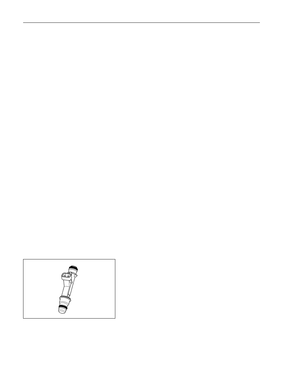
FUEL INJECTOR

The group fuel injection fuel injector is a solenoid-operated
device controlled by the ECM. The ECM energizes the
solenoid, which opens a valve to allow fuel delivery.
The fuel is injected under pressure in a conical spray pattern at
the opening of the intake valve. Excess fuel not used by the
injectors passes through the fuel pressure regulator before
being returned to the fuel tank.
A fuel injector which is stuck partly open will cause a loss of
fuel pressure after engine shut down, causing long crank times.

6E1-294  DRIVEABILITY AND EMISSIONS

FUEL METERING SYSTEM

COMPONENTS

The fuel metering system is made up of the following parts:
• The fuel injectors.
• The throttle body.
• The fuel rail.
• The fuel pressure regulator.
• The ECM.
• The crankshaft position (CKP) sensor.
• The idle air control (IAC) valve.
• The fuel pump.
• The fuel pump relay.

Basic System Operation

The fuel metering system starts with the fuel in the fuel tank.
An electric fuel pump, located in the fuel tank, pumps fuel to
the fuel rail through an in-line fuel filter. The pump is designed
to provide fuel at a pressure above the pressure needed by the
injectors. A fuel pressure regulator in the fuel rail keeps fuel
available to the fuel injectors at a constant pressure. A return
line delivers unused fuel back to the fuel tank. Refer to Section
6C
 for further information on the fuel tank, line filter, and fuel
pipes.

FUEL METERING SYSTEM PURPOSE

The basic function of the air/fuel metering system is to control
the air/fuel delivery to the engine. Fuel is delivered to the
engine by individual fuel injectors mounted in the intake
manifold near each intake valve.
Following are applicable to the vehicle with closed Loop
System:
The ECM monitors signals from several sensors in order to
determine the fuel needs of the engine. Fuel is delivered under
one of several conditions called  "modes."  All modes are
controlled by the ECM.
The main control sensor is the heated oxygen sensor (HO2S)
located in the exhaust system. The HO2S tells the ECM how
much oxygen is in the exhaust gas. The ECM changes the
air/fuel ratio to the engine by controlling the amount of time that
the fuel injector is ON. The best mixture to minimize exhaust
emissions is 14.7 parts of air to 1 part of gasoline by weight,
which allows the catalytic converter to operate most efficiently.
Because of the constant measuring and adjusting of the air/fuel
ratio, the fuel injection system is called a  "closed loop" system.

DRIVEABILITY AND EMISSIONS  6E1-295

FUEL PRESSURE REGULATOR

The fuel pressure regulator is a diaphragm-operated relief
valve mounted on the fuel rail with fuel pump pressure on one
side and manifold pressure on the other side. The fuel
pressure regulator maintains the fuel pressure available to the
injector at three times barometric pressure adjusted for engine
load. It may be serviced separately.
If the pressure is too low, poor performance and a DTC 44, will

be the result. If the pressure is too high, a DTC 45 will be the

result. Refer to Fuel System Diagnosis for information on

diagnosing fuel pressure conditions.

FUEL PUMP ELECTRICAL CIRCUIT

When the key is first turned ON, the ECM energizes the fuel
pump relay for two seconds to build up the fuel pressure
quickly. If the engine is not started within two seconds, the
ECM shuts the fuel pump off and waits until the engine is
cranked. When the engine is cranked and the 58X crankshaft
position signal has been detected by the ECM, the ECM
supplies 12 volts to the fuel pump relay to energize the electric
in-tank fuel pump.
An inoperative fuel pump will cause a  "no-start"  condition. A
fuel pump which does not provide enough pressure will result
in poor performance.

FUEL RAIL

The fuel rail is mounted to the top of the engine and distributes
fuel to the individual injectors. Fuel is delivered to the fuel inlet
tube of the fuel rail by the fuel lines. The fuel goes through the
fuel rail to the fuel pressure regulator. The fuel pressure
regulator maintains a constant fuel pressure at the injectors.
Remaining fuel is then returned to the fuel tank.

6E1-296  DRIVEABILITY AND EMISSIONS

IDLE AIR CONTROL (IAC) VALVE

The purpose of the idle air control (IAC) valve is to control
engine idle speed, while preventing stalls due to changes in
engine load. The IAC valve, mounted in the throttle body,
controls bypass air around the throttle plate. By moving the
conical valve (pintle) in (to decrease air flow) or out (to increase
air flow), a controlled amount of air can move around the
throttle plate. If the RPM is too low, the ECM will retract the IAC
pintle, resulting in more air moving past the throttle plate to
increase the RPM. If the RPM is too high, the ECM will extend
the IAC pintle, allowing less air to move past the throttle plate,
decreasing the RPM.
The IAC pintle valve moves in small steps called counts.
During idle, the proper position of the IAC pintle is calculated by
the ECM based on battery voltage, coolant temperature,
engine load, and engine RPM. If the RPM drops below a
specified value, and the throttle plate is closed, the ECM
senses a near-stall condition. The ECM will then calculate a
new IAC pintle valve position to prevent stalls.
If the IAC valve is disconnected and reconnected with the
engine running, the idle RPM will be wrong. In this case, the
IAC must be reset. The IAC resets when the key is cycled on
ON then OFF. When servicing the IAC, it should only be
disconnected or connected with the ignition OFF.
The position of the IAC pintle valve affects engine start-up and
the idle characteristics of the vehicle. When the ECM detects
the 175 rpm higher engine revolution than desires engine rpm,
this malfunction detects an error in the IAC control logic.
Diagnostic Trouble code 35 will be set.

RUN MODE (APPLICABLE TO CLOSED LOOP

SYSTEMS)

The run mode has the following two conditions:
• Open loop
• Closed loop
When the engine is first started, the system is in  "open loop"
operation. In  "Open Loop,"  the ECM ignores the signal from
the heated oxygen sensor (HO2S). It calculates the air/fuel
ratio based on inputs from the TP, ECT, and MAP sensors.
The system remains in  "Open Loop"  until the following
conditions are met:
• The HO2S has a varying voltage output showing that it is hot

enough to operate properly (this depends on temperature).

• The ECT has reached a specified temperature.
• A specific amount of time has elapsed since starting the

engine.

• Engine speed has been greater than a specified RPM since

start-up.

The specific values for the above conditions vary with different

engines and are stored in the programmable read only memory

(PROM). When these conditions are met, the system enters

"closed loop"  operation. In  "closed loop,"  the ECM calculates

the air/fuel ratio (injector on-time) based on the signal from the

HO2S. This allows the air/fuel ratio to stay very close to 14.7:1.


Content   ..  114  115  116  117   ..