Isuzu D-Max / Isuzu Rodeo (TFR/TFS). Manual - part 965


  Index      Ford     Isuzu D-Max / Isuzu Rodeo TFR/TFS series - service repair manual 1997-2003 year


Search            


Content   ..  963  964  965  966   ..


Isuzu D-Max / Isuzu Rodeo (TFR/TFS). Manual - part 965


4C1-30  FRONT WHEEL DRIVE
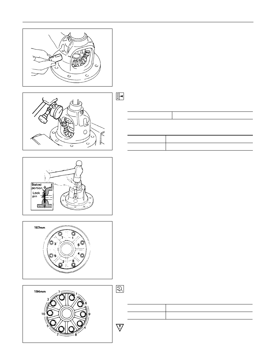
5. Cross Pin

(1) Be sure to install the cross pin so that it is in alignment with

the lock pin hole in the differential cage.

(2) Adjust the backlash between the side gear and the pinion

gear.

mm(in)

Backlash

0.03 - 0.08 (0.001 - 0.003)

Thickness of thrust washers available

mm(in)

167 mm

1.05, 1.15, 1.25 (0.041, 0.043, 0.049)

194 mm

1.00, 1.05, 1.10 (0.039, 0.041, 0.043)

6. Lock Pin
After lock pin installation, stake the cage to prevent discharge
of the lock pin.

7. Ring Gear
When installing the ring gear, apply LOCTITE 271 or equivalent
to the threaded hole and bolt.

8. Bolt

Tighten the bolts in diagonal sequence as illustrated.

Bolt Torque

N

m (kgf

m/lb

ft)

167 mm

78.5 

±

 9.8 (8 

±

 1/57.9 

±

 7.2)

194 mm

107.9 

±

 9.8 (11 

±

 1/79.6 

±

 7.2)

Note :
Discard used bolts and install new ones.
For 167 mm
Note that all bolts have a left hand thread.

FRONT WHEEL DRIVE  4C1-31

  MAJOR COMPONENTS

Reassembly Steps

1. Diff. carrier

2. Outer bearing outer race

3. Inner bearing outer race

4. Adjust shim

5. Inner bearing

6. Collapsible spacer
7. Pinion gear
8. Outer bearing

9. Oil seal

10. Dust cover

11. Flange

12. Flange nut and washer

13. Adjust shim

14. Side bearing

15. Bearing outer race
16. Diff. cage assembly

17. Bearing cap

18. Bolt

19. Axle case

20. Differential assembly

21. Bolt

4C1-32  FRONT WHEEL DRIVE

Important Operations

2. Outer Bearing Outer Race
Installer : 5-8522-0048-0 (167 mm)

(J-29038)
9-8522-1141-0 (194 mm)
(J-24256)

Grip

: 5-8840-0007-0

(J-8092)

3. Inner Bearing Outer Race
Installer : 5-8522-0049-0 (167 mm)

(J-29039)
9-8522-1274-0 (194 mm)

Grip

: 5-8840-0007-0

(J-8092)

4. Adjust Shim
Adjustment of drive pinion mounting distance
(1) Apply gear oil to the inner and outer drive pinion bearing.

Clean the pinion setting gage set.

Then install the gage set together with the inner and outer

bearings.

For 167 mm

1

Pilot

: 5-8840-2092-0

(J-23597-28)

2

Nut and bolt : 5-8840-0127-0

(J-21777-43)

3

Rear pilot

: 5-8840-02091-0

(J-23597-27)

4

Gage plate : 5-8840-2090-0

(J-23597-26)

For 194 mm

1

Pilot

: 5-8840-2085-0

(J-21777-42)

2

Nut and bolt : 5-8840-2089-0

(J-23597-9)

4

Gage plate : 5-8840-2087-0

(J-23597-7)

FRONT WHEEL DRIVE  4C1-33

Tighten the nut to the specified torque.

N

m (kgf

m/lb

ft)

New bearing

2.26 (23/20)

Used bearing

0.98 - 1.18

(10 - 12/8.7 - 10.4)

(2) Clean the side bearing bores.  Install the dial indicator with

the discs and Arbor.  Install and tighten the bearing caps to

the specified torque.

Torque

N

m (kgf

m/lb

ft)

167 mm

68.7 

±

 9.8 (7.0 

±

 1.0/50.6 

±

 7.2)

194 mm

98.1 

±

 9.8 (10.0 

±

 1.0/72.3 

±

 7.2)

For 167 mm

1

Dial indicator : 5-8840-0126-0

(J-8001)

2

Disc (2 pcs.) : 5-8840-2086-0

(J-23597-4)

3

Arbor

: 5-8840-0128-0

(J-23597-1)

4

Gage plate

: 5-8840-2090-0

(J-23597-26)

For 194 mm

1

Dial indicator : 5-8840-0126-0

(J-8001)

2

Disc (2 pcs.) : 5-8840-2088-0

(J-23597-8)

3

Arbor

: 5-8840-0128-0

(J-23597-1)

4

Gage plate

: 5-8840-2087-0

(J-23597-7)


Content   ..  963  964  965  966   ..