Isuzu D-Max / Isuzu Rodeo (TFR/TFS). Manual - part 816


  Index      Ford     Isuzu D-Max / Isuzu Rodeo TFR/TFS series - service repair manual 1997-2003 year


Search            


Content   ..  814  815  816  817   ..


Isuzu D-Max / Isuzu Rodeo (TFR/TFS). Manual - part 816


6D3–18 STARTING AND CHARGING SYSTEM (6VD1 3.2L)
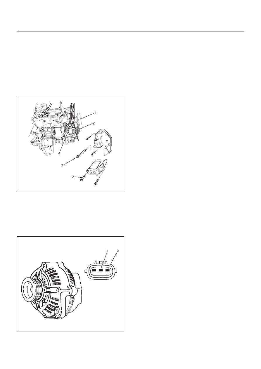
Generator

Removal

1. Disconnect battery ground cable.
2. Move drive belt tensioner to loose side using wrench

then remove drive belt (1).

3. Disconnect the wire from terminal “B” and disconnect

the connector (4).

4. Remove generator fixing bolt (3).
5. Remove generator assembly (2).

060RW002

Inspection

1. Disconnect the wiring connector from generator.
2. With the engine stopped, turn starter switch to “ON”

and connect a voltmeter between connector terminal
L (2) and ground or between terminal IG (1) and
ground.

066RW001

If voltage is not present, the line between battery and
connector is disconnected and so requires repair.

3. Reconnect the wiring connector to the generator, run

the engine at middle speed, and turn off all electrical
devices other than engine.

4. Measure battery voltage. If it exceeds 16V, repair or

replace the generator.

5. Connect an ammeter to output terminal of generator,

and measure output current under  load by turning on
the other electrical devices (eg., headlights). At this
time, the voltage must not be less than 13V.

Installation

1. Install generator assembly to the position to be

installed.

2. Install generator assembly and tighten the fixing bolts

to the specified torque.

Torque:
M10 bolt: 41 N·m (4.2 kg·m/30 lb ft)
M8 bolt: 21 N·m (2.1 kg·m/15 lb ft)

3. Connect wiring harness connector and direct terminal

“B”.

4. Move drive belt tensioner to loose side using wrench,

then install drive belt to normal position.

5. Reconnect battery ground cable.

6D3–19

STARTING AND CHARGING SYSTEM (6VD1 3.2L)

Disassembled View

066RW007

Legend

(1) Pulley Nut
(2) Pulley
(3) Front Cover Assembly
(4) Rotor Assembly
(5) Rear End Cover

(6) Rectifier
(7) Terminal Insulator and Nut
(8) Regulator Assembly
(9) Brush Holder Assembly

(10) Rear Cover

Disassembly

1. Terminal insulator and nut(2).

6D3–20 STARTING AND CHARGING SYSTEM (6VD1 3.2L)

2. Remove three nuts(1) on the rear cover and a nut on

terminal B and insulator, then remove the rear
cover(3).

060RW005

3. Remove two screws that fix the brush holder(5) and

rectifier, then remove the brush holder assembly(4).

060RW004

4. Remove three screws on the IC regulator, then the IC

regulator assembly(6).

060RW003

5. Remove four screws that fix rectifier(7) and stator

lead wires.

066RW004

6D3–21

STARTING AND CHARGING SYSTEM (6VD1 3.2L)

6. Secure the pulley directly in the vise between two

copper plates, and remove the nut and pulley.

066RS010

7. Remove four nuts(8) that secure the front cover

assembly and rear end cover, and an insulator(9).

066RW005

8. Use the puller to remove the rear end cover.
9. Rotor assembly

066RS012

10. Pull the rotor assembly(10) off the front cover

assembly(12) using a bench press(11).

066RW006


Content   ..  814  815  816  817   ..