Isuzu D-Max / Isuzu Rodeo (TFR/TFS). Manual - part 547
6A – 26 ENGINE MECHANICAL
FUEL SYSTEM
Fuel Filter
Replacement Procedure
1. Place the end of the vinyl hose (beneath the drain
plug) in a container.
2. Open the drain plug.
3. Operate the priming pump several times to drain water
from the fuel filter.
4. Close the drain plug.
5. Operate the priming pump and check for fuel leakage.
6. Check that the water level warning light is off.
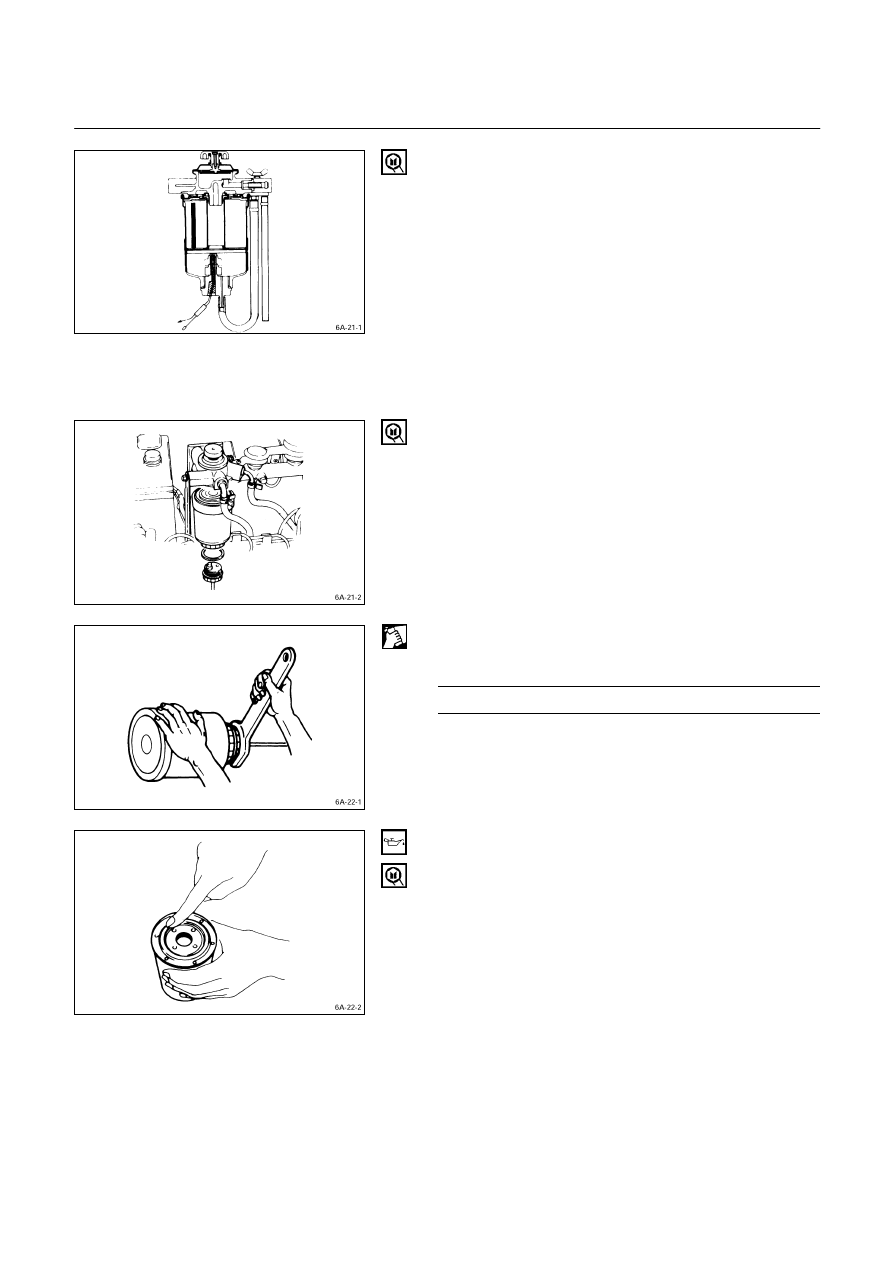
Fuel Filter Replacement Procedure
1. Remove the fuel filter by turning it counterclockwise
with a filter wrench.
Filter Wrench: 5-8840-0253-0 (J-22700)
2. Remove the level sensor from the filter by turning it
counterclockwise with a wrench.
3. Install the level sensor to the water separator body
with wrench.
Level Sensor Torque
kg·m (lb.in/N·m)
1.3 (113/13)
4. Clean the water separator cover fitting faces.
This will allow the new fuel filter to seat properly.
5. Apply a light coat of engine oil to the O-ring.
6. Turn in the fuel filter until the sealing face comes in
contact with the O-ring.
7. Turn in the fuel filter an additional 2/3 of a turn with a
filter wrench.
Filter Wrench : 5-8840-0253-0 (J-22700)