Isuzu D-Max / Isuzu Rodeo (TFR/TFS). Manual - part 546


  Index      Ford     Isuzu D-Max / Isuzu Rodeo TFR/TFS series - service repair manual 1997-2003 year


Search            


Content   ..  544  545  546  547   ..


Isuzu D-Max / Isuzu Rodeo (TFR/TFS). Manual - part 546


6A – 22  ENGINE MECHANICAL 


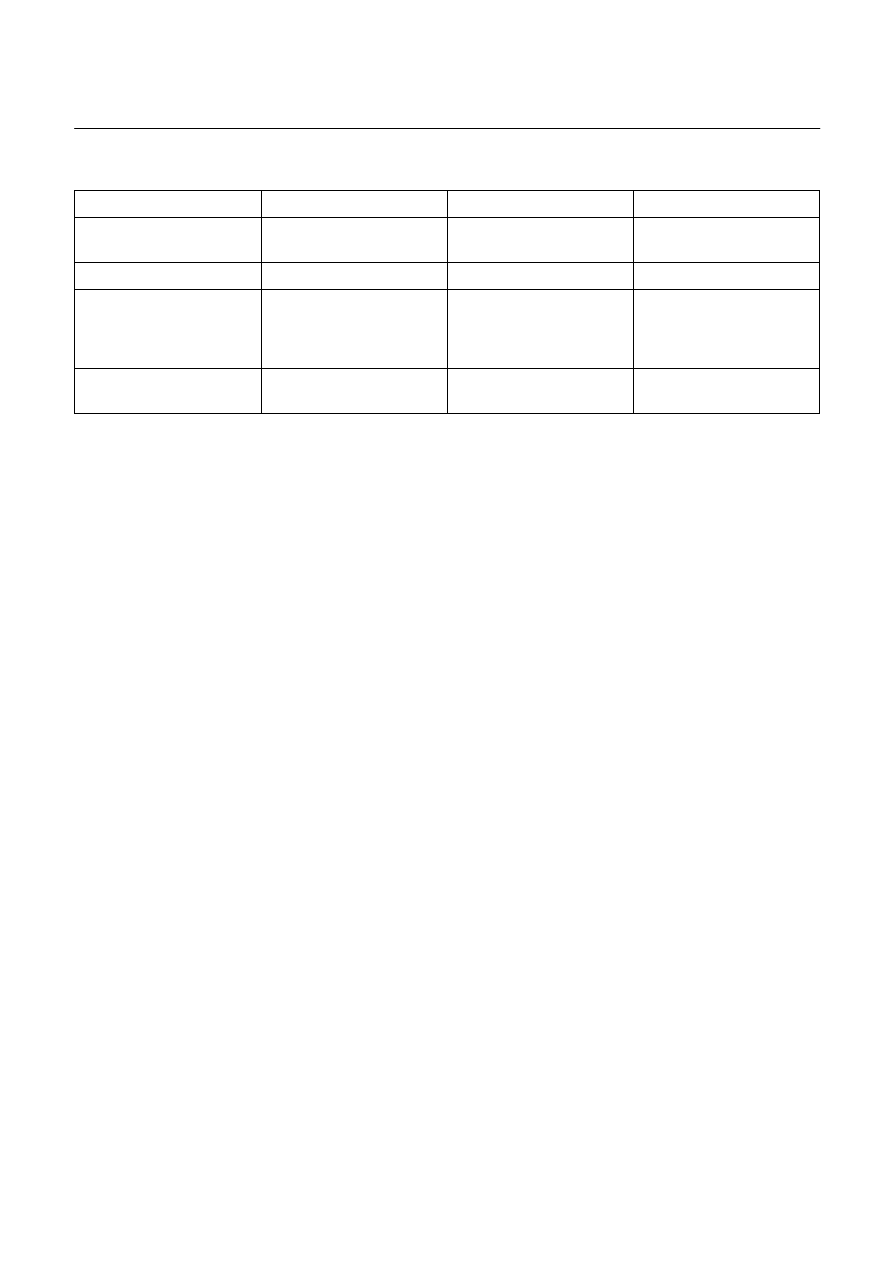
RECOMMENDED LIQUID GASKET 

Type Brand 

Name 

Manufacturer 

Remarks 

RTV* 

Silicon Base 

ThreeBond 1207B 
ThreeBond 1207C 

Three Bond 
Three Bond 


  Water Base 

ThreeBond 1141E 

Three Bond 


 Solvent 

ThreeBond 

1104 

BelcoBond 4 
BelcoBond 401 
BelcoBond 402 

Three Bond 
Isuzu 
Isuzu 
Isuzu 


 Anaerobic 

LOCTITE 

515 

LOCTITE 518 

Loctite 
Loctite 

Recommended for 
transaxle repairs 

 
* RTV : Room Temperature Vulcanizer 
 
Note: 

1.  It is very important that the liquid gaskets listed above or their exact equivalent be used on the 

vehicle. 

2.  Be careful to use the specified amount of liquid gasket. 

Follow the manufacturer’s instructions at all times. 

3.  Be absolutely sure to remove all lubricants and moisture from the connecting surfaces before 

applying the liquid gasket. 
The connecting surfaces must be perfectly dry. 

4.  LOCTITE 515 and LOCTITE 518 harden upon contact with a metal surface. 

Do not apply LOCTITE 515 or LOCTITE 518 between two metal surfaces having a clearance of 
greater than 0.25 mm (0.01 in). Poor adhesion will result. 

ENGINE MECHANICAL   6A – 23 


LOCTITE APPLICATION PROCEDURE 

LOCTITE Type 

LOCTITE Color 

Application Steps 

LOCTITE 242 

Blue 

LOCTITE 262 

Red 

LOCTITE 270 

Green 

LOCTITE 271 

Red 

1.  Completely remove all lubricant and moisture from the bolts and the 

female threaded surfaces of the parts to be joined. 
The surfaces must be perfectly dry. 

2.  Apply LOCTITE to the bolts. 


3.  Tighten the bolts to the specified torque. 

4.  Wait at least one hour before continuing the installation procedure. 

LOCTITE 515 

Violet 

1.  Completely remove lubricant and moisture from the connecting 

surfaces. 
The surfaces must be perfectly dry. 

2.  Apply a 2.0 – 2.5 mm bead of LOCTITE to one of the connecting 

surfaces. 
There must be no gaps in the bead. 

3.  Tighten the bolts to the specified torque. 

4.  Let the joined parts set for at least thirty minutes. 


6A – 24  ENGINE MECHANICAL 


SERVICING 

Servicing refers to general maintenance procedures to be performed by qualified service personnel. 


MODEL IDENTIFICATION 

Engine Serial Number 

The engine number is stamped on the front left hand side 
of the cylinder body. 


AIR CLEANER 

Element cleaning procedures will vary according to the 
condition of the element. 


Oil Wetted (Viscous Type) Paper Element 

The air cleaner has an oil wetted paper element. No 
servicing is required until the replacement interval is 
reached. Never attempt to clean the element, no matter 
how dirty may appear. The element is designed to provide 
normal filtering efficiency until it becomes due for 
replacement. Refer to the Item “Service and Maintenance” 
in the Owner’s and Driver’s Manual for general service 
information. 


Dust Fouled Element 

Rotate the element with your hand while applying 
compressed air to the inside of the element. This will blow 
the dust free. 
Compressed air pressure must not exceed 7 kg/cm

2

 (100 

psi/690 kPa). 


Carbon and Dust Fouled Element 

1.  Prepare a cleaning solution of Isuzu Genuine Element 

Cleaner (Donaldson D1400) diluted with water. 

2.  Submerge the element in the solution for twenty 

minutes. 

A06RY00006


ENGINE MECHANICAL   6A – 25 


3.  Remove the element from the solution and rinse it well 

with running water. 


Water pressure must not exceed 2.8 kg/cm

2

 (40 

psi/270 kPa). 


4.  Dry the element in a well ventilated area. 

An electric fan will hasten drying. 

Note: 
Do not use compressed air or an open flame to dry the 
element quickly. Damage to the element will result. 
It will usually take two or three days for the element to 
dry completely. Therefore, it is a good idea to have a 
spare on hand to use in the interim.


LUBRICATING SYSTEM 

Main Oil Filter (Cartridge Type Paper Element) 
Replacement Procedure 

1.  Loosen the drain plug to drain the engine oil. 
2.  Wait a few minutes and then retighten the drain plug. 
3.  Loosen the used oil filter by turning it counterclockwise 

with a filter wrench. 


4.  Clean the oil cooler fitting face. This will allow the new 

oil filter to seat properly. 

5.  Apply a light coat of engine oil to the O-ring. 
6.  Turn in the new oil filter until the filter O-ring is fitted 

against the sealing face. 

7.  Use the filter wrench to turn in the filter an additional 1 

and 1/8 turns. 
Filter Wrench: 5-8840-0200-0 (4JB1T, 4JG2T, 4JA1T, 

4JA1TC, 4JH1TC) 

: 5-8840-0201-0 (4JA1) 


8.  Check the engine oil level and replenish to the 

specified level if required. 

Replenished Engine Oil 

lit (US/UK gal)

× 2 

4JA1, 4JA1T 

4JB1T 

× 4 

6.5 (1.7/1.4) 

× 2 

6.5 (1.7/1.4) 

4JG2T, 4JA1-TC 

4JH1TC 

× 4 

7.3 (1.9/1.6) 


9.  Start the engine and check for oil leakage from the 

main oil filter. 


Content   ..  544  545  546  547   ..