Isuzu D-Max / Isuzu Rodeo (TFR/TFS). Manual - part 367


  Index      Ford     Isuzu D-Max / Isuzu Rodeo TFR/TFS series - service repair manual 1997-2003 year


Search            


Content   ..  365  366  367  368   ..


Isuzu D-Max / Isuzu Rodeo (TFR/TFS). Manual - part 367


7A-16  AUTOMATIC TRANSMISSION (AW30-40LE) 

DIAGNOSIS 

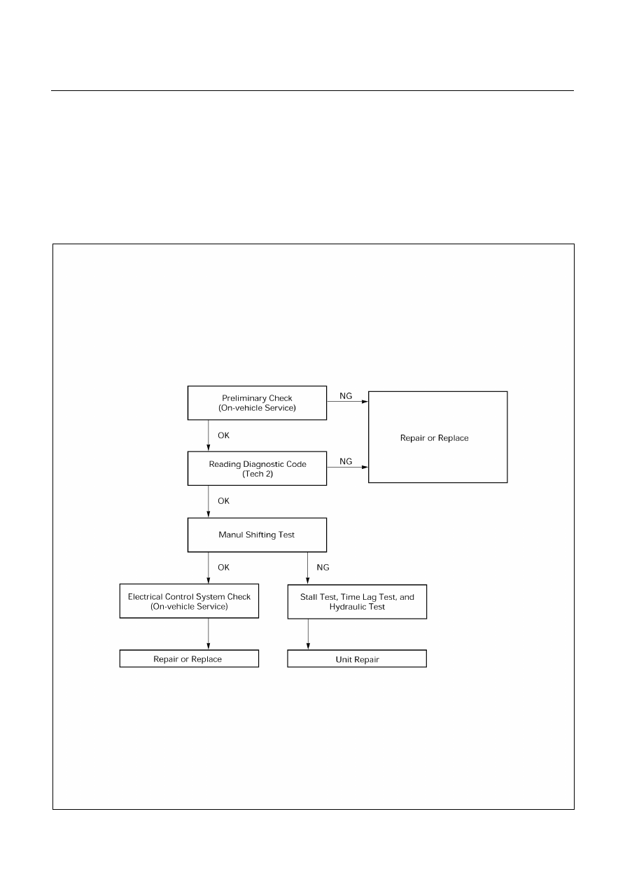
BASIC TROUBLESHOOTING 

AW30-40LE transmission, called Electronic Controlled Transmission (ECT), differs from oil pressure control type 
transmissions in that it is controlled by a microcomputer. Accordingly, its troubleshooting procedure differs also. 
Before troubleshooting an ECT, first determine whether the problem is electrical or mechanical. To do this, just refer 
to the basic troubleshooting flowchart provided below. 
If the cause is already known, using the basic troubleshooting chart below along with the troubleshooting chart 
should speed the procedure. 


F07R200005

AUTOMATIC TRANSMISSION (AW30-40LE)  7A-17 


UBS 


825R200084 

TFR/S 


825R200085 


SELF DIAGNOSIS 

Warning to the driver 

・  When trouble has occurred to throttle position sensor, 

vehicle speed sensor, or solenoid, “CHECK TRANS” lamp 
is blinked (1.25 Hz) even during driving to warn the driver.

・  The trouble is recorded by trouble code is TCM. 

・  When temporary trouble has been shooted, the “CHECK 

TRANS” lamp stops blinking. This blinking can be stopped 
by setting the ignition key off. But the trouble code remains 
memorized in TCM. 


F07LV002 


7A-18  AUTOMATIC TRANSMISSION (AW30-40LE) 

UBS (RHD) 


740RY00013 

UBS (LHD) 


740RY00014 


Self-diagnosis code display 

・  For quick search for faulty parts, 6 different items of 

trouble code are indicated by “CHECK TRANS” lamp 
blinking. 

・  The storaged trouble codes can be identified by shorting

the terminals No.11 and No.4 or 5 (ground) of diagnosis
connector with a lead wire. 


TFR/S 


740R200046 


AUTOMATIC TRANSMISSION (AW30-40LE)  7A-19 


F07LV001 


Indication Method: 
(1) Terminals No.11 and No.4 or 5 (ground) of diagnosis

connector are short circuited. 

(2)  Turn the ignition key to the ON position. 
(3)  In case there no trouble, normal code is indicated. 
(4) In case a plurality of trouble codes have occurred at a 

time, each code is indicated three times in numerical
order. 


NOTE: 
Power line runs through diagnosis connector. 
Be careful shorting with a lead wire, etc. 
(The vehicle side of control module may be damaged.) 
For identification of trouble code, connect Tech 2 to 
diagnosis connector.


Clear of trouble code memory 
1.  Clear the trouble code memory using F1: Clear DTC 

Information for Tech 2. 

2.  Shorting terminals for 3-4 second between No.11 and 

No.4 or 5 (ground) of diagnosis connectors after the
ignition key tuned to the on position for 1 second of longer.

・  After erasing trouble code, check to see if the normal code 

is outputted through running test. 


Trouble code 


Trouble 

Code 

Mode 

Diagnostic area and Failure 

11 

Vehicle speed sensor 2 (Transmission mounting) 
Open or shorted circuit 

21 

Throttle position sensor input 
Open or shorted circuit 

24 

Vehicle speed sensor 1 (In speedometer) 
Open or shorted circuit 

31 

Shift solenoid S1 
Open or shorted circuit 

32 

Shift solenoid S2 
Open or shorted circuit 

33 


Lock-up solenoid S3 
Open or shorted circuit 

F07L100030 


Content   ..  365  366  367  368   ..