Isuzu D-Max / Isuzu Rodeo (TFR/TFS). Manual - part 237
ENGINE DRIVEABILITY AND EMISSIONS
6E–189
6
Using the DVM and check the VSS signal.
1. Ignition “On”, vehicle “Run (lift up)”.
2. Measure the VSS output voltage at sensor, meter,
immobiliser control unit (if equipped) and ECM.
Does the tester indicate specified value?
If a oscilloscope is available, monitor the VSS signal.
Does the oscilloscope indicate correct wave form?
Refer to
Diagnostic Aids
and Go to Step
21
Refer the table
Step
Action
Value(s)
Yes
No
Measurement Position
Voltage (V)
(AC Range)
If No
Good
VSS terminal 3 & GND
Approximately
7.0 V at 20km/h
Go to
Step 7
Meter B24 connector 9 &
GND
Go to
Step 11
Meter B24 connector 10 &
GND
Go to
Step 13
Immobiliser control unit B68
connector 6 & GND
Go to
Step 14
Immobiliser control unit B68
connector 8 & GND
Approximately
4.8 V at 20km/h
Go to
Step 16
ECM C56 (J2) connector 23 &
GND
Go to
Step 17
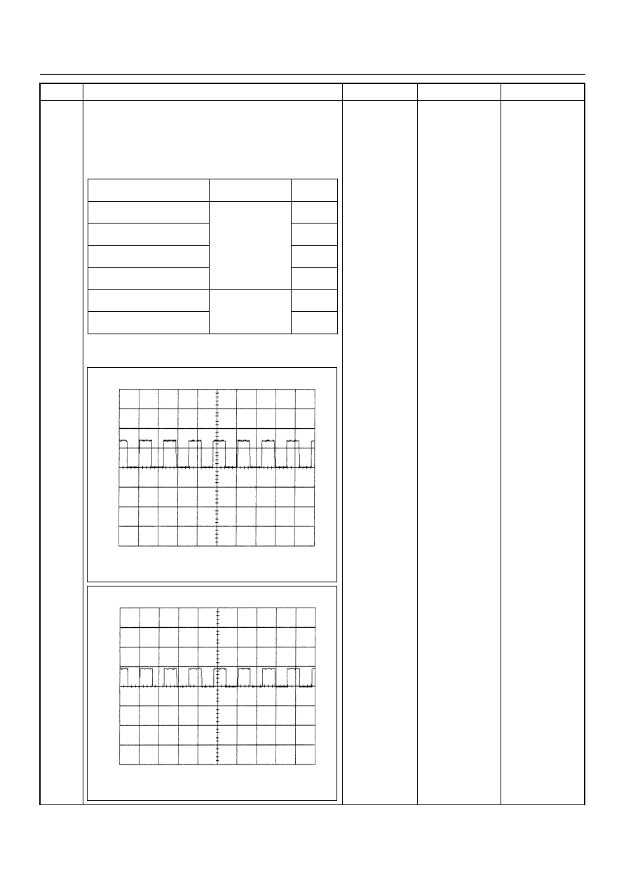
Vehicle Speed Sensor Reference Wave Form
0V
→
Measurement Scale: 10V/div 50ms/div
Measurement Condition: Vehicle speed 20km/h
Measurement Terminal: At Vehicle Speed Sensor
Vehicle Speed Sensor Reference Wave Form
0V
→
Measurement Scale: 10V/div 50ms/div
Measurement Condition: Vehicle speed 20km/h
Measurement Terminal: At Engine Control Module