Isuzu D-Max / Isuzu Rodeo (TFR/TFS). Manual - part 218


  Index      Ford     Isuzu D-Max / Isuzu Rodeo TFR/TFS series - service repair manual 1997-2003 year


Search            


Content   ..  216  217  218  219   ..


Isuzu D-Max / Isuzu Rodeo (TFR/TFS). Manual - part 218


ENGINE DRIVEABILITY AND EMISSIONS

6E–113

7

Repair the open or short to ground circuit between the
ECM and MAP sensor 
Was the problem solved?

Verify repair

Go to Step 11

8

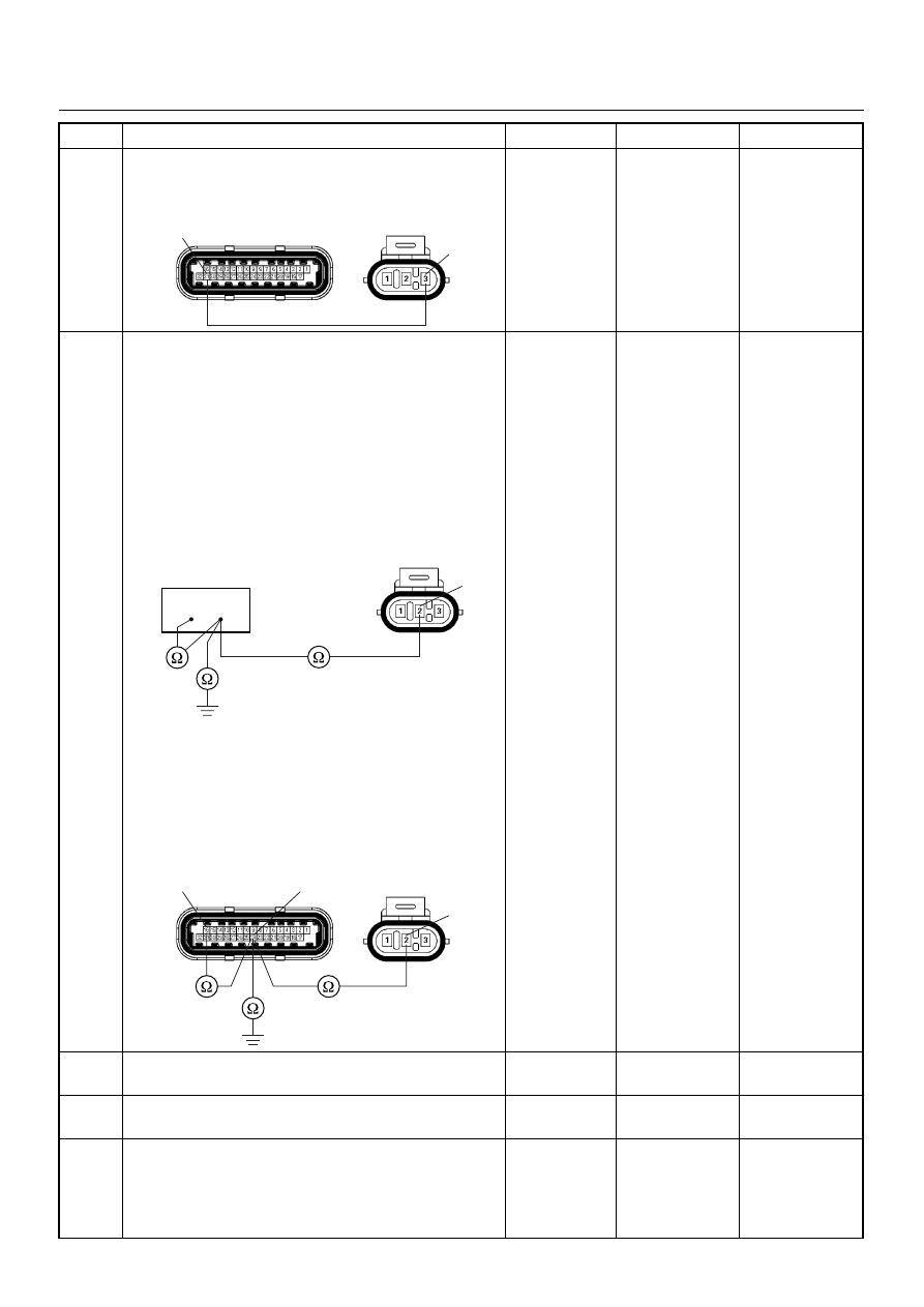
Using the DVM and check the MAP sensor signal
circuit.
Breaker box is available: 

1. Ignition “Off”, engine “Off”. 

2. Install the breaker box as type A. (ECM

disconnected) Ref. 6E-80.

3. Disconnect MAP sensor connector. 

4. Check the circuit for open, short to sensor ground

or short to ground circuit. 

Was the problem found?

Breaker box is not available: 

1. Ignition “Off”, engine “Off”. 

2. Disconnect the MAP sensor connector and ECM

connector. 

3. Check the circuit for open, short to sensor ground

or short to ground circuit. 

Was the problem found?

Repair faulty 

harness and 

verify repair

Go to Step 9

9

Substitute a known good MAP sensor and recheck. 
Was the problem solved?

Go to Step 10

Go to Step 11

10

Replace the MAP sensor. 
Is the action complete?

Verify repair

11

Is the ECM programmed with the latest software
release? 
If not, download the latest software to the ECM using
the “SPS (Service Programming System)”. 
Was the problem solved?

Verify repair

Go to Step 12

Step

Action

Value(s)

Yes

No

31

3

E85

E60(J1)

2

E85

16

24

16

24

2

E85

E60(J1)

6E–114

ENGINE DRIVEABILITY AND EMISSIONS

12

Replace the ECM. 
Is the action complete? 
IMPORTANT:  The replacement ECM must be
programmed. Refer to section of the Service
Programming System (SPS) in this manual. 
Following ECM programming, the immobiliser system
(if equipped) must be linked to the ECM. Refer to
section 11 “Immobiliser System-ECM replacement” for
the ECM/Immobiliser linking procedure.

Verify repair

Step

Action

Value(s)

Yes

No

ENGINE DRIVEABILITY AND EMISSIONS

6E–115

DIAGNOSTIC TROUBLE CODE (DTC) P0108 MANIFOLD ABSOLUTE 

PRESSURE CIRCUIT HIGH INPUT

Condition for setting the DTC and action taken when the DTC sets

Circuit Description

The manifold absolute pressure (MAP) sensor responds
to changes in intake manifold pressure. The MAP
sensor signal voltage to the engine control module
(ECM) varies from below 2 volts at idle (low manifold
pressure) to above 4 volts with the ignition ON, engine
not running or at wide-open throttle (high manifold
pressure).
A “speed density” method of determining engine load is
used on the 2.4L engine. This is calculated using inputs

from the MAP sensor, RPM, CKP Sensor, and the
Intake Air Temperature (IAT) sensor. The MAP sensor is
the main sensor used in this calculation, and measuring
engine load is its main function.
The ECM monitors the MAP signals for voltages outside
the normal range (10-104 kpa) of the MAP sensor. If the
ECM detects a MAP signal voltage that is excessively
high, Diagnostic Trouble Code P0108 will be set.

Code

Type

DTC Name

DTC Setting Condition

Fail-Safe (Back Up)

P0108

A

Manifold Absolute Pressure Circuit 
High Input

1. No DTC relating to TPS. 
2. Throttle position is below 15% if engine 

speed is below 2500rpm, or throttle posi-
tion is below 35% if engine speed is more 
than 2500rpm. 

3. Engine run time is longer than 10 seconds. 
4. MAP sensor output is more than 103KPa.

The ECM uses default manifold absolute 
pressure value based on engine speed 
and throttle position.

Manifold
Absolute
Pressure(MAP) Sensor

Crankshaft
Position(CKP)
                 Sensor

µP

0.5
GRY/
BLU

J1-16

0.5
GRY/
RED

J1-24

0.5
YEL/
RED

J1-31

0.5
BLK/
WHT

J1-1

0.5
BLK/
WHT

J1-2

0.5
BLK/
WHT

J1-17

0.5
BLK

J1-6

0.5
WHT

J1-21

INLET
MANIFOLD

5 Volts
Reference

Engine
Control
Module
(ECM)

6E–116

ENGINE DRIVEABILITY AND EMISSIONS

Diagnostic Aids

Check for the following conditions:

• Poor connection at ECM - Inspect harness

connectors for backed-out terminals, improper
mating, broken locks, improperly formed or damaged
terminals, and poor terminal-to-wire connection.

• If these codes are also set, it could indicate a

problem with the 5 Volt reference circuit.

• Damaged harness - Inspect the wiring harness for

damage; an open circuit, a short to ground, or a short
to voltage. If the harness appears to be OK, observe
the MAP display on the Tech 2 while moving
connectors and wiring harnesses related to the
sensor. A change in the display will indicate the
location of the fault.

Diagnostic Trouble Code (DTC) P0108 

Manifold Absolute Pressure Circuit High Input

Step

Action

Value(s)

Yes

No

1

Was  the  “On-Board Diagnostic (OBD) System Check”
performed?

Go to Step 2

Go to On Board 

Diagnostic 

(OBD) System 

Check

2

1. Connect the Tech 2. 

2. Review and record the failure information. 

3. Select  “F0: Read DTC Infor By Priority” in “F0:

Diagnostic Trouble Code”. 

Is the DTC P0108 stored as “Present Failure”?

Go to Step 3

Refer to 

Diagnostic Aids 

and Go to Step 

3

3

1. Using the Tech2, ignition “On” and engine “Off”. 

2. Select “Clear DTC Information” with the Tech2 and

clear the DTC information. 

3. Operate the vehicle and monitor the “F5: Failed

This Ignition” in “F2: DTC Information”.

Was the DTC P0108 stored in this ignition cycle?

Go to Step 4

Refer to 

Diagnostic Aids 

and Go to Step 

4

4

Check for poor/faulty connection at the MAP sensor or
ECM connector. If a poor/faulty connection is found,
repair as necessary. 
Was the problem found?

Verify repair

Go to Step 5

5

Visually check the MAP sensor. 
Was the problem found?

Go to Step 11

Go to Step 6

16

31

24

E85

E60(J1)


Content   ..  216  217  218  219   ..