Content .. 2035 2036 2037 2038 ..
Isuzu D-Max / Isuzu Rodeo (TFR/TFS). Manual - part 2037
3B-38 STEERING
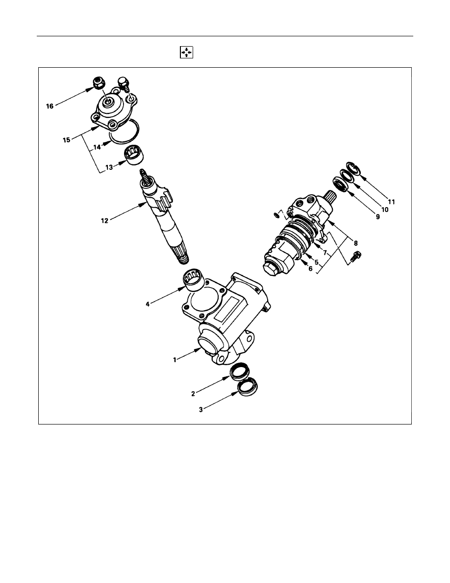
REASSEMBLY
Reassembly Steps
1. Gear box
V
2. Gasket
V
3. Seal
4. Needle bearing
V
5. Gasket
V
6. Seal ring
V
7. Gasket
V
8. Ball nut and valve housing assembly
V
9. Oil seal
V
10. Seal ring
V
11. Retaining ring
V
12. Sector shaft
13. Needle bearing
14. O-ring
V
15. Top cover assembly
V
16. Lock nut