Isuzu D-Max / Isuzu Rodeo (TFR/TFS). Manual - part 2032


  Index      Ford     Isuzu D-Max / Isuzu Rodeo TFR/TFS series - service repair manual 1997-2003 year


Search            


Content   ..  2030  2031  2032  2033   ..


Isuzu D-Max / Isuzu Rodeo (TFR/TFS). Manual - part 2032


3B-18  STEERING

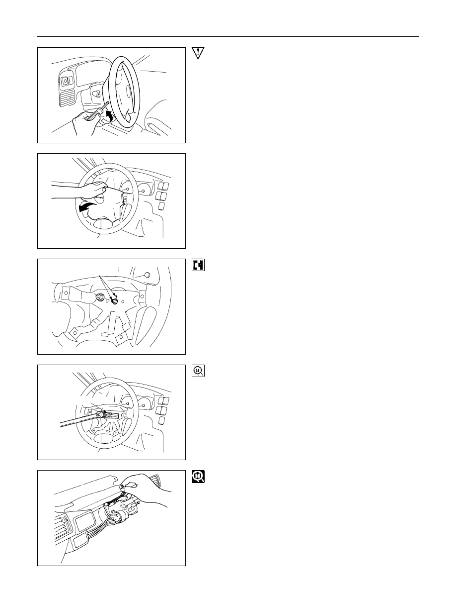
Important Operations - Removal

1., 1a. Horn Shroud

(1) Remove the arrowed screw at the rear side of the steering

wheel.

(2) Pull up the pad along the direction shown in the left figure

and remove from the steering wheel.

Setting mark

3., 3a. Steering Wheel

(1) Apply a setting mark across the steering wheel and shaft so

parts can be reassembled in their original position.

5-8521-0016-0

(2) Steering Wheel Puller : 5-8521-0016-0

(J-29752)

Note :
Never apply blow to the setting wheel in direction of the
shaft by using a hammer or other impact tools in an
attempt to remove the steering wheel, the setting shaft is
designed as an energy absorbing unit.

8. Steering Lock and Bearing
Remove the steering lock assembly using the inner hex
wrench.

STEERING  3B-19

Turn the ignition/starter key to OFF position.
Note :
With the steering in lock position, the steering lock
assembly cannot be removed.

9. Steering Column Assembly
Apply a setting mark across the universal joint and steering
shaft to reassemble of the parts in their original position.
Note :
A Setting mark can be easily punched if the shaft is
withdrawn a little by loosening the steering shaft universal
joint.

Important Operations - Installation

9. Steering Column Assembly

Steering Column Torque

N

m (kgf

m/Ib

ft)

16.7 

+2.9

0

 (1.7 

+0.3

0

/12.3 

+2.1

0

)

Align the setting marks made when removing.

8. Steering Lock and Bearing
Turn the ignition/starter key to OFF position.
With the steering in lock position, the steering lock assembly
cannot be installed.

3B-20  STEERING

Install the steering lock assembly using the inner hex wrench.

Setting mark

3., 3a. Steering Wheel

(1) Align the setting marks made when removing.

(2) Apply grease to contact ring.

Note :
Never apply blow to the setting wheel in direction of the
shaft by using a hammer or other impact tools in an
attempt to install the steering wheel, the setting shaft is
designed as an energy absorbing unit.

2., 2a. Nut

Steering Wheel Nut Torque

N

m (kgf

m/Ib

ft)

34.3

±

4.9 (3.5

±

0.5/25.3

±

3.6)

1. Horn shroud

(1) Remove the bracket from the nail at the lower side of pad

assembly with a screw driver.

(2) Install the bracket (removed at procedure 1) onto the

steering wheel sub assembly with a screw.

(3) Connect the harnesses, then, hang the nail of the pad

assembly onto the plate of the steering wheel sub

assembly, and install the pad carefully so that the nail is not

separated from the bracket. (See the lowest figure.)

STEERING  3B-21

STEERING UNIT

GENERAL DESCRIPTION

MANUAL STEERING UNIT

The steering gear is mainly comprised of the sector gear and the worm nut assembly.
There are many recirculating balls installed to the ball groove (way) between the worm nut and the steering worm
shaft.
The steering gear's high mechanical efficiency provides very light steering.
Racks machined into the worm nut side face engage the fan shaped sector gear to transfer the steering wheel
applied torque to the pitman arm.


Content   ..  2030  2031  2032  2033   ..