Content .. 1974 1975 1976 1977 ..
Isuzu D-Max / Isuzu Rodeo (TFR/TFS). Manual - part 1976
4C2-24 FRONT DRIVING AXLE
DISASSEMBLY
• Before disassembly, jack up the front of vehicle and
support frame with jack stands.
• Remove the disc brake caliper assembly and hang it on
the frame with wires (Refer to Section 5A "HYDRAULIC
FOUNDATION BRAKES")
1. Bolt
Before removal, shift transfer lever into "2H" position.
2. Hub cap
3. Snap Ring and Shim
4. Hub flange
5. Lock Washer and Lock Screw
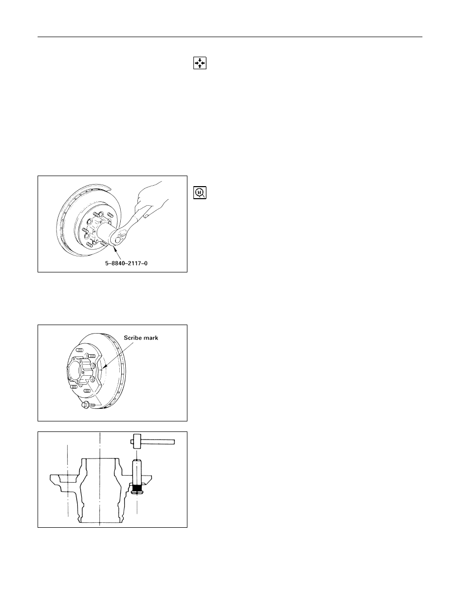
6. Hub nut
Wrench: 5-8840-2117-0 (J-36827)
7. Hub and Disc Assembly
8. Outer Bearing Outer Race
9. Oil Seal
10.Inner Bearing Outer Race
11.Bolt
If necessary, replace the wheel pin in the following manner.
1) Apply a scribe mark to disc to hub.
2) Clamp the hub and disc assembly in a vise, using
protective pads. Remove the 6 disc-to-hub retaining
bolts.
12.Wheel Pin
Place hub on a suitable work surface and remove the wheel
studs, as required, using a hammer.