Content .. 1971 1972 1973 1974 ..
Isuzu D-Max / Isuzu Rodeo (TFR/TFS). Manual - part 1973
4C2-12 FRONT DRIVING AXLE
DISASSEMBLY
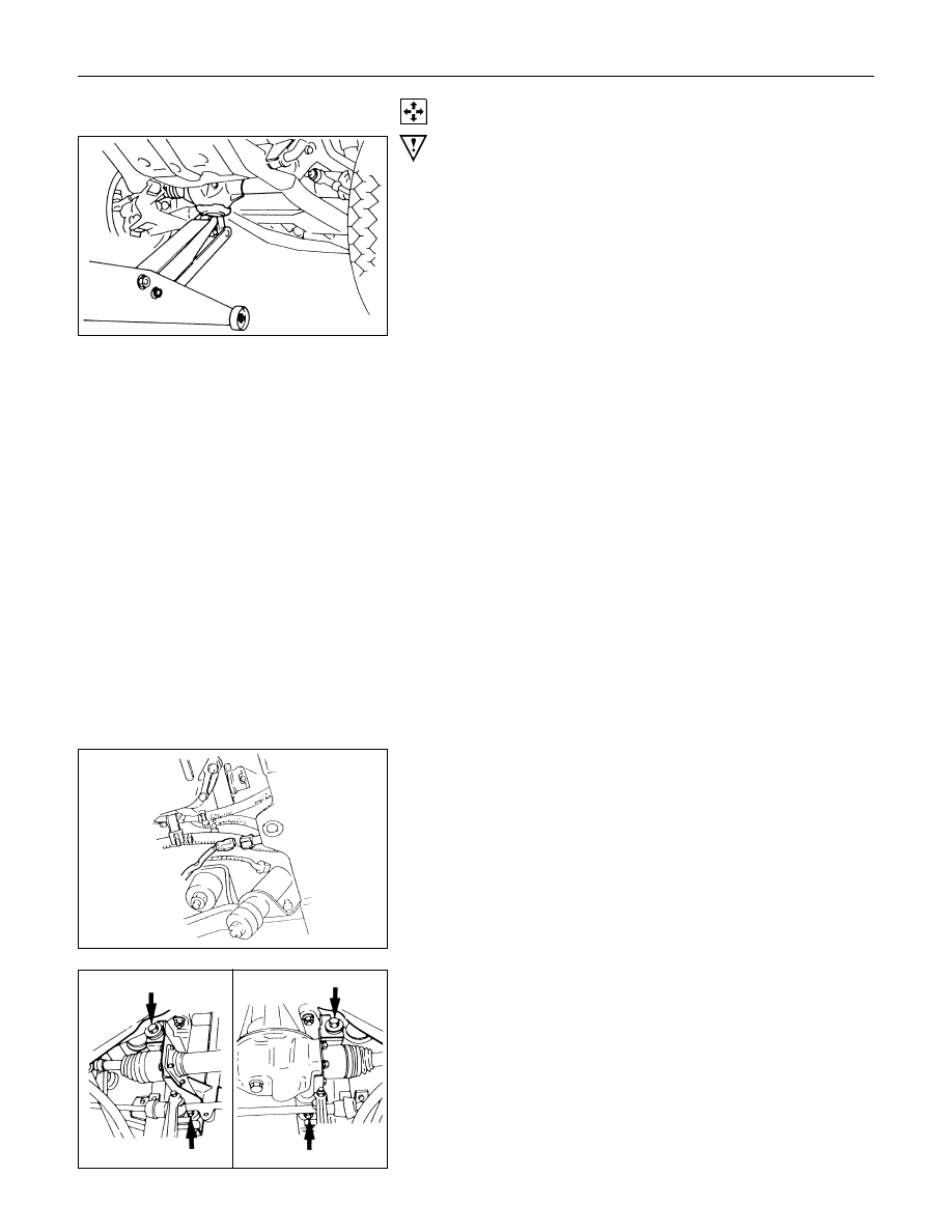
WARNING:
DURING THE WORK, BE SURE THAT THE DIFF CASE IS
SUPPORTED BY THE JACK.
Preparations:
• Jack up the vehicle and support it using jack stands.
• Remove the tire and wheel.
• Remove the drain bolt to drain differential oil.
• Remove the brake caliper fixing bolt and hang the caliper.
Refer to Section 5A2 "HYDRAULIC FOUNDATION
BRAKES".
1. Hub Assembly (Disc, Back Plate and Knuckle)
• Remove the locking hub. Refer to this Section "FRONT
HUB AND DISC".
• Disconnect the knuckle and the suspension arm. Refer to
Section 3C "FRONT SUSPENSION".
2. Steering Link and Arm Assembly
Refer to Section 3B3 "STEERING LINKAGE".
3. Suspension Crossmember
4. Propeller Shaft
Refer to Section 4A "PROPELLER SHAFT".
5. Protector (w/shift on the fly system)
6. Breater Hose
• Disconnect breather hose from front drive axle.
7. Connector (w/shift on the fly system)
• Disconnect actuator connector.
• Disconnect shift detective switch connector.
8. Mounting Bolt and Nut