Isuzu D-Max / Isuzu Rodeo (TFR/TFS). Manual - part 1837


  Index      Ford     Isuzu D-Max / Isuzu Rodeo TFR/TFS series - service repair manual 1997-2003 year


Search            


Content   ..  1835  1836  1837  1838   ..


Isuzu D-Max / Isuzu Rodeo (TFR/TFS). Manual - part 1837


7A1-10  CONSTRUCTION AND FUNCTION 

INPUT SHAFT 

 The input shaft has some oil holes, through which lubricating ATF is supplied to the torque converter, 

bearings, etc. 

 The input shaft is fitted the turbine runner in the torque converter, reverse & high clutch drum and rear sun 

gear by means of the spline.  Therefore, the engine driving force received by the torque converter is 
transmitted to the reverse & high clutch drum and rear sun gear. 


OUTPUT SHAFT 

 The output shaft has some oil holes, through which the lubricating ATF is supplied to the bearings, 

planetary gear unit, etc. 

 The output shaft transmits the engine driving force from the planetary gear to the propeller shaft. 

 The front internal gear is fitted with the rear carrier assembly by spline.    The parking gear is also fitted by 

spline.    By fixing this gear mechanically, the output shaft is fixed as required when parking the vehicle. 


GEAR SHIFTING MECHANISM 

 The JR405E consists of two sets of planetary gears, three multiple plate clutches, two multiple plate 

brakes and a one-way clutch. They are activated in different combinations in any of four forward and one 
reverse gear positions. 


Principle of gear shifting (Figure 12) 

 Planetary gears have the advantage of a compact configuration because of the way they are constructed 

with a single central shaft. 

 Also, unlike the manual transmission gears that require changing of gear mesh, the gear ratio of the 

planetary gears can be changed more easily by locking, releasing or rotating only some of their parts. 

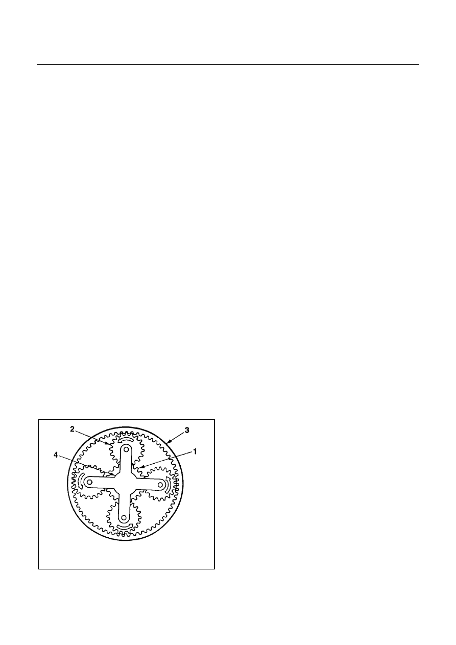
 A planetary gear is made up of a sun gear (1) at its center and pinion gears (2) each of which rotates 

about its own center and also along the sun gear, as shown. They are all called in the internal gear (3). 

 Also, since the pinion gears are further supported by the planetary carrier (4), they rotate as a unit in the 

same direction and at the same rate. 

 As shown above, each planetary gears are constructed of three elements; a sun gear, pinion gears, and 

internal gear and a planetary carrier. Gear shifting is achieved by conditioning two of the three elements 
namely the sun gear, internal gear and the planetary carrier. 

 The planetary gears are locked by the clutch, brake and one-way clutch according to the gear shifting. 


1. Sun Gear 

2. Pinion Gear 

3. Internal Gear 

4. Planetary Carrier 


Figure 12. Planetary Gear 

CONSTRUCTION AND FUNCTION  7A1-11 


 The JR405E consists of two sets of planetary gears, which are called front planetary gear and rear 

planetary gear. 

 The sun gear of front planetary gear is fixed to the drive plates of 2-4 brake and reverse clutch. 

 The planetary carrier of front planetary gear is fixed to the drum of low clutch, the drive plates of low & 

reverse brake and the hub of high clutch. 

 The internal gear of front planetary gear and the planetary carrier of rear planetary gear are connected as 

one, and they are fixed to output shaft.   

 The sun gear of rear planetary gear is fixed to input shaft. 

 The internal gear of rear planetary gear is fixed to the hub of low clutch. 


Clutch and Brake 

 Basic structure of the clutch and brake is shown in the figures below. 

 In the figure A, the clutch plates (drive plate and driven plate) are in the fluid so that they slip against each 

other transmitting no power. 

 Figure B shows the condition where the oil pressure is acting on the piston.    The clutch plates are fitted 

to each other under pressure transmitting the rotations of the clutch drum to the clutch hub. 

 When the oil pressure is removed from the piston, the clutch returns to the condition in the figure A by the 

return spring. 


Figure 13. Basic Construction of Clutch and Brake 

 
Low Clutch, High Clutch and Reverse Clutch (Multi-Plate Clutch) 

 The multi-plate clutch is composed of drive plates and driven plates.    By applying the oil pressure onto 

the end surface of the plates, the clutch is engaged or disengaged.    The oil pressure is adjusted with the 
control valve according to the signal from the TCM. 

 All clutches use dish plates to prevent uncontrolled operation of the clutches when engaged, causing a 

shock. 

 For the reverse clutch, a piston check ball is used to release the oil pressure for the purpose of preventing 

the clutch drag due to oil pressure generated by residual ATF because of the centrifugal force while the 
clutch is racing (under no oil pressure). 

 For the low clutch and high clutch, a centrifugal balance chamber always full of ATF is provided to offset 

the excessive oil pressure, for the purpose of preventing the clutch drag due to oil pressure generated by 
residual ATF because of the centrifugal force while the clutch is racing (under no oil pressure). 

 The solenoid in the control valve is driven based on the speed change signal from TCM and moves the 

shift valve, thereby engaging the drive plate and driven plate through the piston of each clutch. 

 Resultantly, elements of the planetary gear unit are combined. 

 When the oil pressure is removed, the piston returns to the original position by the force of the return 

spring. 

7A1-12  CONSTRUCTION AND FUNCTION 


Figure 14. Basic Construction of Low Clutch 

and High Clutch 


Figure 15. Basic Construction of Reverse Clutch


Figure 16. Construction of Low Clutch 


Figure 17. Construction of High Clutch 


Figure 18. Construction of Reverse Clutch 


CONSTRUCTION AND FUNCTION  7A1-13 


2-4 Brake and Low & Reverse Brake (Multi-Plate Brake) 

 The multi-plate brake is composed of drive plates and driven plates.    By applying the oil pressure onto 

the end surface of the plates, the clutch is engaged or disengaged.    The oil pressure is adjusted with the 
control valve according to the signal from the TCM. 

 All brakes use dish plates to prevent uncontrolled operation of the clutches when engaged, causing a 

shock. 

 The solenoid in the control valve is driven based on the speed change signal from TCM and moves the 

shift valve, thereby engaging the drive plate and driven plate through the piston of each clutch. 

 Resultantly, rotation of each element of the planetary gear unit is fixed. 

 When the oil pressure is removed, the piston returns to the original position by the force of the return 

spring. 


Figure 19. Construction of 2-4 Brake 


Figure 20. Construction of Low & Reverse Brake


Low One-way Clutch 

 The low one-way clutch employs the sprag which locks the counterclockwise rotation of the front planetary 

carrier and rear internal gear. 

 The one-way clutch outer race is fitted with the low clutch drum and the inner race with the transmission 

case. 

 The outer race rotates freely clockwise but, when it attempts to rotate counterclockwise, the sprag 

functions to lock the outer race. 

 When the vehicle is traveling in 1st gear in the D, 3 or 2range, the low one-way clutch locks the rear 

internal gear via the low clutch. It is left free in the 2nd, 3rd or 4th gear position. 


Figure 21. Construction of Low One-way Clutch 


Content   ..  1835  1836  1837  1838   ..