Content .. 1793 1794 1795 1796 ..
Isuzu D-Max / Isuzu Rodeo (TFR/TFS). Manual - part 1795
UNIT REPAIR (JR405E) 7A4-47
Free length – 36.4 mm (1.433 in)
Linear diameter – 1.2 mm (0.047 in)
21C&L-SUB31
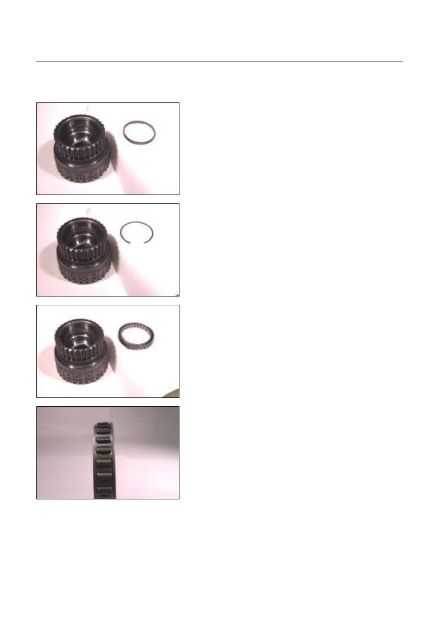
Reassembly steps
Coat the parts with ATF before installing them.
1. Bearing
Install the bearing into the low clutch drum.
22C&L-SUB30
2. Snap ring
Install the snap ring to the low clutch drum.
23C&L-SUB28
3. Low one-way clutch
Install the low one-way clutch to the low clutch drum.
24C&L-SUB33
NOTE:
The flanged side of the low one-way clutch must face the
outside.