Isuzu D-Max / Isuzu Rodeo (TFR/TFS). Manual - part 1779


  Index      Ford     Isuzu D-Max / Isuzu Rodeo TFR/TFS series - service repair manual 1997-2003 year


Search            


Content   ..  1777  1778  1779  1780   ..


Isuzu D-Max / Isuzu Rodeo (TFR/TFS). Manual - part 1779


ON-VEHICLE SERVICE (JR405E)  7A3-5 

THROTTLE POSITION SENSOR 


P1010052

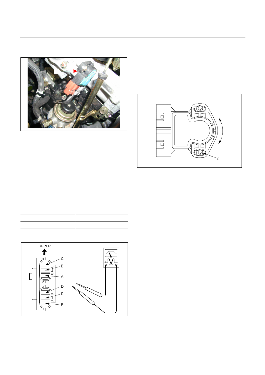
The throttle position sensor (1) is fitted on the throttle 
valve body. 


Adjust 

1.  Turn the starter switch to the “ON” position. 

2. Measure the voltage between TPS connector

terminals (B) (output) and (A) (ground). 

Note: 

  Do not remove the sensor connector. 

  Make sure that power source (5.0 

±

  0.01  V)  is

measured between TPS connector terminals (C) and

(A) before measurement at step 2. 

Standard voltage : 


Throttle Angle 

TPS 

Idling (0%) 

0.2 - 0.3 V 

WOT (100%) 

3.4 – 4.1 V 


RTW37ASH0013


3.  If the reading is beyond the specified value, loosen 

the throttle position sensor fixing bolts, and turn it 

right or left, so that the specified output voltage be 

obtained. 


After adjusting, tighten the throttle position sensor 

fixing screws (2). 

826R300013


7A3-6  ON-VEHICLE SERVICE (JR405E) 

INHIBITOR SWITCH 

The inhibitor switch is attached to the right side of the 
transmission. 


Inspect 

1.  Block the wheels. 

2.  Disconnect the negative battery cable. 

3.  Disconnect the harness connectors. 

4. Use a ohmmeter to check the inhibitor switch

continuity between the following terminals as shown

in figure. 

5.  Place the select lever in the “N” range. 

249R300001

6.  Move the select lever to either side. 

  Check the inhibitor switch continuity between the

terminals shown in Step (4). 


The continuity readings should remain fairly steady

as the select lever is moved. 

  If there is no continuity or the continuity is

intermittent, the inhibitor switch must be adjusted. 


Adjust 

1.  Disconnect the shift calbe from the lever. 

2.  Loosen the inhibitor switch bolts. 

3.  Use the inhibitor switch set plate to align the neutral

holes (manual shaft and inhibitor switch). 


Turn the inhibitor switch to adjust it. 


Inibitor switch set plate: 5-8840-2763-0 

Note: 
Inhibitor switch adjustment is very important. 

If the inibitor switch is not correctly adjusted, the 
automatic transmission will not function normally. 


4.  Tighten the 2 inhibitor switch bolts to the specified 

touque. 

 Torque: 

5.5 

N·m (48 lb·in) 

47INH-SW01

5.  Connect the shift cable to the lever. 

6.  Connect the harness connector. 


Remove or Disconnect 

1.  Remove the cable bracket (1) from the transmission.

2.  Disconnect the shift cable (2) from the lever (3). 

3.  Disconnect the harness connectors. 

4.  Remove the inhibitor switch bolts. 

5. 

Remove the inhibitor switch (4) from the 

transmission. 


238R300001


ON-VEHICLE SERVICE (JR405E)  7A3-7 

Install or Connect 

1.  Install the inhibitor switch (4) to the transmission. 


Temporarily tighten the inhibitor switch bolts. 

2.  Move the manual shaft select lever to the “N” range.
 

249R300002

3.  Use the inhibitor switch set plate to align the neutral

holes (manual shaft and inhibitor switch). 


Turn the inhibitor switch to adjust it. 


Inhibitor switch set plate: 5-8840-2763-0 

Note: 
Inhibitor switch adjustment is very important. 

If the inhibitor switch is not correctly adjusted, the 
automatic transmission will not function normally. 

4.  Tighten the 2 inhibitor switch bolts to the specified 

torque. 

 Torque: 

5.5 

N·m (48 lb·in) 

47INH-SW01

5.  Install the cable bracket (1) to the transmission. 

6.  Connect the shift cable (2) to the lever (3). 

7.  Connect the harness connector. 

8.  Connect the negative battery cable. 

9.  Remove the wheel blocks. 


7A3-8  ON-VEHICLE SERVICE (JR405E) 

SPEED SENSOR 

The speed sensor is attached to the right side of the 
transmission. 

240L300001

Legend 

1. Inhibitor switch 

2. Speed sensor 

3. Turbine sensor 


Inspect 

1.  During the driving at speed of 20km/h (12mph) with 

“L” range in low gear, measure the voltage between 

the TCM connector terminals (B13) and (B5) with a 

digital voltmeter. 


Standard voltage : approx. 7V (AC range) 

826R300014

2.  If the voltage is out of the standard value, check the 

speed sensor pole piece for presence of foreign 

meterials and the speeed sensor cable for short or 

open circuit. 


Result of the inspection is normal, replace the speed 

sensor. 


Torque: 6 N·m (52 lb·in) 


TURBINE SENSOR 

The turbine sensor is attached to the right side of the 
transmission. 


Inspect 

1.  During the driving at speed of 20km/h (12mph) with

“L” range in low gear, measure the voltage between

the TCM connector terminals (B3) and (B5) with a

digital voltmeter. 


Standard voltage : approx. 7V (AC range) 

2.  If the voltage is out of the standard value, check the

turbine sensor pole piece for presence of foreign

materials and the turbine sensor cable for short or

open circuit. 

  Result of the inspection is normal, replace the

turbine sensor. 


Torque: 6 N·m (52 lb·in) 


Content   ..  1777  1778  1779  1780   ..