Isuzu D-Max / Isuzu Rodeo (TFR/TFS). Manual - part 1687


  Index      Ford     Isuzu D-Max / Isuzu Rodeo TFR/TFS series - service repair manual 1997-2003 year


Search            


Content   ..  1685  1686  1687  1688   ..


Isuzu D-Max / Isuzu Rodeo (TFR/TFS). Manual - part 1687


6A-46 ENGINE MECHANICAL (C24SE, C22NE, 22LE, 20LE)

Installation

1.

Install the cylinder head gasket.

Mark "OBEN/TOP" on top and turn it towards timing side
of engine.

2.

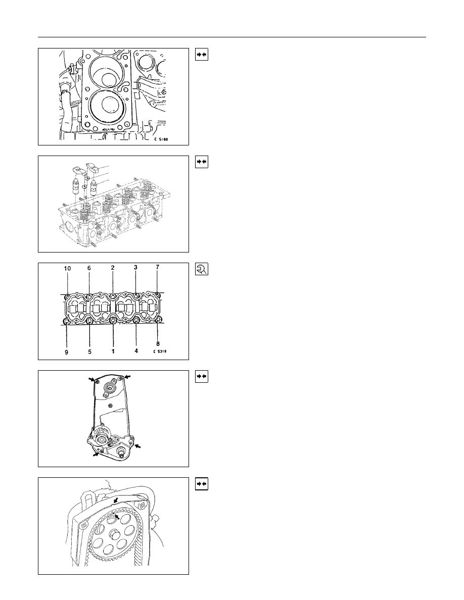
Place cylinder head on cylinder block.

1
2
3

Installation

1.

Insert the hydraulic valve lifters (3), thrust pieces (2) and
cam followers (1) with MoS2 paste.

Note allocation.

2.

Apply a bead of Sealing Compound TB1207C to sealing
surface of cylinder head.

3.

Install the camshaft housing on cylinder head.

Torque-Angle Method

Cylinder head and camshaft housing with new cylinder head
bolts to cylinder block.

Cylinder head bolts in sequence shown.

Installation

1.

Install the rear toothed belt cover to camshaft housing.

2.

Install the camshaft pulley to camshaft.

3.

Install the camshaft housing cover to housing.

Installation

1.

Install the toothed belt on camshaft pulley.

See operation "Timing  Adjust".

2.

Install the front toothed belt cover.

ENGINE MECHANICAL (C24SE, C22NE, 22LE, 20LE) 6A-47

Installation

1.

Install the fastening bolts.

2.

Loosen the lower alternator fastening bolt.

3.

Install the alternator, power steering and V-belts.

Cylinder Head, Disassemble and Assemble

Removal

1.

Remove the hydraulic valve lifters.

Lay aside in installation positions.

2.

Remove the spark plugs, exhaust manifold and intake
manifold from cylinder head.

Removal

1.

Mark valves.

2.

Remove the tension valve springs with 5-8840-2594-0
(1).

3.

Remove valve keepers, valve spring cap and valve
spring.

Removal

1.

Remove the valve and valve stem seal.

2.

Remove the valve spacer ring (1-exhaust) and valve
spring seat (2-intake).

3.

Remove valve from cylinder head.

Clean

Sealing surfaces.

6A-48 ENGINE MECHANICAL (C24SE, C22NE, 22LE, 20LE)

Inspection

Sealing surfaces for plane surface, guides, sliding and bearing
points for wear-see operation “Cylinder Head. Overhaul”.

Installation

1.

Coat the valves with engine oil and insert in cylinder
head.

2.

Install the valve spacer ring or valve rotator(exhaust) and
valve spring seal(intake).

3.

Push the accompanying assembly sleeve onto valve
stem and coat with engine oil.

4.

Insert a new valve stem seal with 5-8840-2601-0 (1).

5.

Drive the valve stem seal carefully in to stop with light
hammer blow.

Installation

1.

Install the valve springs and valve spring caps.

2.

Install the tension valve springs with 5-8840-2594-0 (1),
valve keeper.

Important!

Note markings made on valves.

Tighten (Torque)

Exhaust manifold and intake manifold with new gaskets to
cylinder head.

Thermostat housing with new seal ring to cylinder head:

Tighten (Torque)

Spark plugs with spark plug wrench to cylinder head.

Installation

1.

Coat hydraulic valves lifters (1) with oil.

2.

Insert them in cylinder head.

Note installation position.

ENGINE MECHANICAL (C24SE, C22NE, 22LE, 20LE) 6A-49

Valve, Grind

Valves can be reused once or twice after regrinding-only if
there are no crater-like burns on the valve cone.
Excessive grinding can cause the upper valve head edge to
become too thin.

Important!

Valve stem protection must not exceed dimension “A”-use 5-
8840-2596-0.
Do not regrind valve stem ends.
For all valve reworking note that angle of valve head is 44

° and

the valve seat 45

°-see also “Technical Data”.

Valve, Grind In

Grind-In the valve to improve valve seating.
Grind-In by rhythmically lifting valves and turning uniformly.
Use commercially available grinding tool.

Important!

Use only fine-grained pastes for grinding.
Lubricate valve stem before grinding in.

Clean

After grinding, carefully clean valve and valve soat.

Valve Guide, Ream

Measure

Diameter of valve guide-dial gauge and internal measuring
instrument.

Important!

Valve oversizes are available ex-works.
Oversize identification, on the valve guide and on the valve
stem end with the following specified identificaton
flgures/letters-see also “Technical Data”.

Identification Mark

Size

Production Customer Service

Reamer

Normal

none

K

0.075 mm

1

K1

0.150mm

2

K2

Ream valve guide from the upper side of the cylinder head to
the next oversize (use 5-8840-2599-0).
After reaming, cross out identification mark and stamp in new
identification mark.


Content   ..  1685  1686  1687  1688   ..