Isuzu D-Max / Isuzu Rodeo (TFR/TFS). Manual - part 161
6E–248
4JH1 ENGINE DRIVEABILITY AND EMISSIONS
• Damaged harness-Inspect the wiring harness for
damage. If the harness appears to be OK, observe
the “Engine Speed” display on the Tech2 while
moving connectors and wiring harness related to the
sensor.
Diagnostic Trouble Code (DTC) P1335 (Symptom Code A) (Flash Code 43)
Engine Speed Output Circuit Malfunction
Step
Action
Value(s)
Yes
No
1
Was the “On-Board Diagnostic (OBD) System Check”
performed?
—
Go to Step 2
Go to On Board
Diagnostic
(OBD) System
Check
2
1. Connect the Tech 2.
2. Review and record the failure information.
3. Select “F0: Read DTC Infor As Stored By ECU” in
“F0: Diagnostic Trouble Codes”.
Is the DTC P1335 (Symptom Code A) stored as
“Present Failure”?
—
Go to Step 3
Refer to
Diagnostic Aids
and Go to Step
3
3
1. Using the Tech 2, ignition “On” and engine “Off”.
2. Select “F1: Clear DTC Information” in “F0:
Diagnostic Trouble Codes” with the Tech 2 and
clear the DTC information.
3. Operate the vehicle and monitor the “F0: Read
DTC Infor As Stored By ECU” in the “F0:
Diagnostic Trouble Codes”.
Was the DTC P1335 (Symptom Code A) stored in this
ignition cycle?
—
Go to Step 4
Refer to
Diagnostic Aids
and Go to Step
4
4
Was the DTC P0335 (Symptom Code B) or P0335
(Symptom Code D) stored at the same time?
—
Go to DTC
Chart P0335
(Symptom
Code B)
(Symptom
Code C)
Go to Step 5
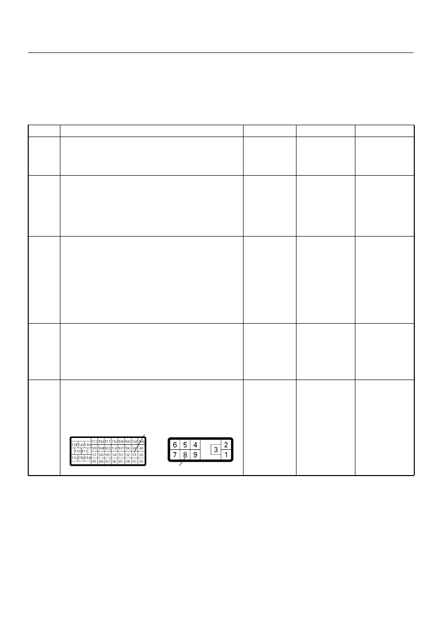
5
Check for poor/faulty connection at the ECM or PSG
(pump control unit) connector. If a poor/faulty
connection is found, repair the faulty terminal.
Was the problem found?
—
Verify repair
Go to Step 6
91
8
C-57(B)
E-6