Isuzu D-Max / Isuzu Rodeo (TFR/TFS). Manual - part 138


  Index      Ford     Isuzu D-Max / Isuzu Rodeo TFR/TFS series - service repair manual 1997-2003 year


Search            


Content   ..  136  137  138  139   ..


Isuzu D-Max / Isuzu Rodeo (TFR/TFS). Manual - part 138


6E–156

4JH1 ENGINE DRIVEABILITY AND EMISSIONS

6

Using the DVM and check the CKP sensor signal.

1. Ignition “On”, engine “On”. 

2. Measure the CKP output voltage at the sensor

and ECM. 

Does the tester indicate standard voltage? 

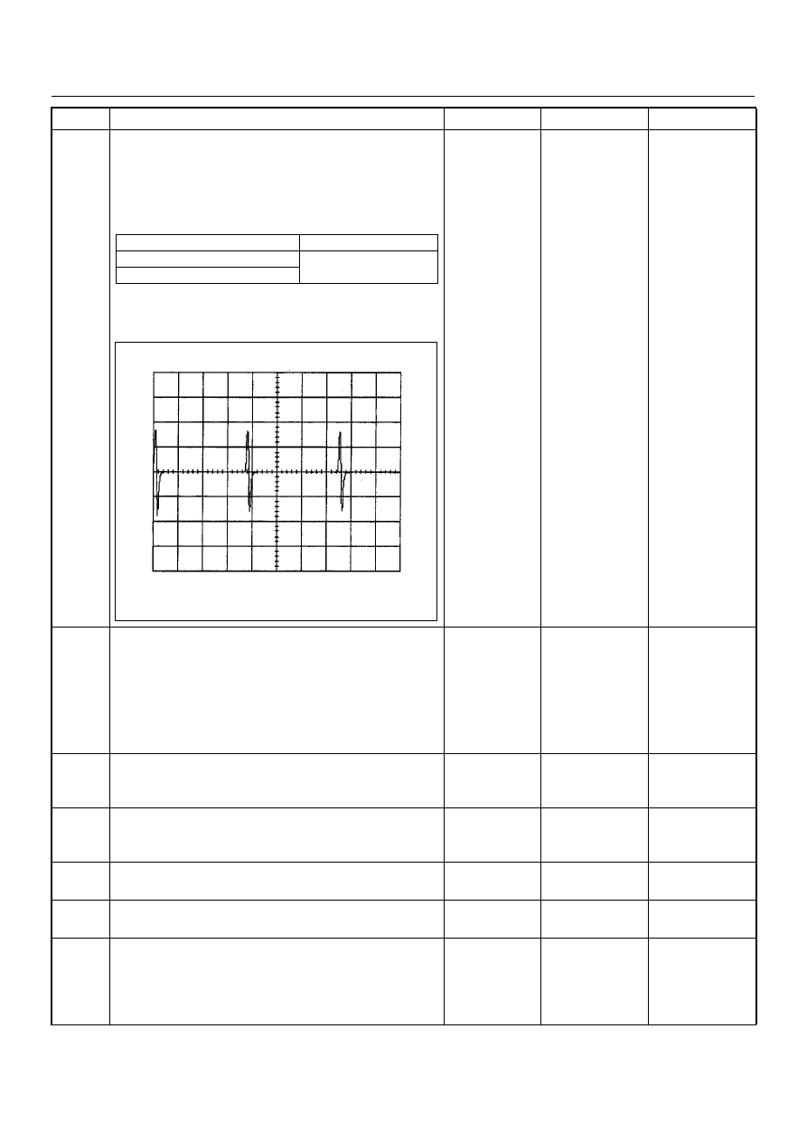
If a oscilloscope is available, monitor the CKP sensor
signal. Does the oscilloscope indicate correct wave
form? 

Go to Step 9

Go to Step 7

7

Remove the CKP sensor from the flywheel housing
and visually check. 
Check for the following conditions. 

• Objects sticking the CKP sensor. 

• Objects sticking the CKP sensor pulser. 
If a problem is found, repair as necessary. 
Was the problem found? 

Verify repair

Go to Step 8

8

Check the CKP sensor shield wire for open or short
circuit. 
Was the problem found?

Repair faulty 
harness and 

verify repair

Go to Step 9

9

Check any accessory parts which may cause electric
interference or magnetic interference. 
Was the problem found?

Remove the 

accessory parts 

and verify repair

Go to Step 10

10

Substitute a known good CKP sensor and recheck. 
Was the problem solved?

Go to Step 11

Go to Step 12

11

Replace the CKP sensor. 
Was the problem solved?

Verify repair

Go to Step 12

12

Is the ECM programmed with the latest software
release? 
If not, download the latest software to the ECM using
the “SPS (Service Programming System)”. 
Was the problem solved?

Verify repair

Go to Step 13

Step

Action

Value(s)

Yes

No

Measurement Point

Voltage (V) (AC Range)

At CKP sensor terminal 2 & 1

Approximately 1.0 V at 
2000rpm

At ECM C57 connector 90 & 98

CKP Sensor Reference Wave Form

0V

Measurement Terminal: 90 (+) 98(-)
Measurement Scale: 20V/div

2.0ms/div

Measurement Condition: Engine speed at 2000rpm

4JH1 ENGINE DRIVEABILITY AND EMISSIONS

6E–157

13

Replace the ECM. 
Is the action complete? 
IMPORTANT: The replacement ECM must be
programmed. Refer to section of the Service
Programming System (SPS) in this manual. 
Following ECM programming, the immobiliser system
(if equipped) must be linked to the ECM. Refer to
section 11 “Immobiliser System-ECM replacement” for
the ECM/Immobiliser linking procedure.

Verify repair

Step

Action

Value(s)

Yes

No

6E–158

4JH1 ENGINE DRIVEABILITY AND EMISSIONS

DIAGNOSTIC TROUBLE CODE (DTC) P0380 (SYMPTOM CODE 4) 

(FLASH CODE 66) GLOW RELAY CIRCUIT VOLTAGE LOW

DIAGNOSTIC TROUBLE CODE (DTC) P0380 (SYMPTOM CODE 8) 

(FLASH CODE 66) GLOW RELAY CIRCUIT VOLTAGE HIGH

Condition for setting the DTC and action taken when the DTC sets

Circuit Description

The voltage on the coil of the relay glow plug is supplied
by the relay engine control module (ECM) main. The
ECM switches glow relay to operate glow plug depends
on the coolant temperature.
In the after glow phase the lamp is not illuminated but
the glow plugs remain active for a certain period
depending on engine coolant temperature.

Diagnostic Aids

An intermittent may be caused by the following:

• Poor connections.

• Misrouted harness.

• Rubbed through wire insulation.

• Broken wire inside the insulation.
Check for the following conditions:

Flash 

Code

Code

Symptom 

Code

MIL

DTC Name

DTC Setting Condition

Fail-Safe (Back Up)

66

P0380

4

ON

Glow Relay Circuit Voltage 
Low

Glow relay circuit open or 
short to ground circuit.

No fail-safe function.

8

ON

Glow Relay Circuit Voltage 
High

Glow relay circuit short to volt-
age circuit.

Resister

A/C
Compressor

ECM
Main Relay

Battery
Voltage

Heater
Relay

Glow
50A

Glow
Relay

Glow
Plug

ECM
10A

0.5
BLU/
RED

0.5
BLK/
BLU
94

0.5
BRN/
RED

0.5
BLK

41

0.5
GRN

33

5.0
RED/
WHT

0.5
BLU/
RED

0.5
BRN/
YEL

0.5
GRY/
YEL

A/C
10A

0.5 BRN

A/C
Compressor
Relay

A/C
Thermo
Relay

0.5
BLU/
RED

5.0
BLK/
RED

Tripple
Pressure
SW

µP

Batt

µP

Batt

IC

Engine
Control
Module
(ECM)

4JH1 ENGINE DRIVEABILITY AND EMISSIONS

6E–159

• Poor connection at ECM-Inspect harness connectors

for backed out terminals, improper mating, broken
locks, improperly formed or damaged terminals, and
poor terminal to wire connection.

• Damaged harness-Inspect the wiring harness for

damage. If the harness appears to be OK, observe
the DTC P0380 display on the Tech2 while moving
connectors and wiring harnesses. A change in the
display will indicate the location of the fault.

Diagnostic Trouble Code (DTC) P0380 (Symptom Code 4) (Flash Code 66) 

Glow Relay Circuit Voltage Low

Step

Action

Value(s)

Yes

No

1

Was  the  “On-Board Diagnostic (OBD) System Check”
performed?

Go to Step 2

Go to On Board 

Diagnostic 

(OBD) System 

Check

2

1. Connect the Tech 2. 

2. Review and record the failure information. 

3. Select “F0: Read DTC Infor As Stored By ECU” in

“F0: Diagnostic Trouble Codes”. 

Is the DTC P0380 (Symptom Code 4) stored as
“Present Failure”?

Go to Step 3

Refer to 

Diagnostic Aids 

and Go to Step 

3

3

1. Using the Tech 2, ignition “On” and engine “Off”. 

2. Select  “F1: Clear DTC Information” in “F0:

Diagnostic Trouble Codes” with the Tech 2 and
clear the DTC information. 

3. Operate the vehicle and monitor the “F0: Read

DTC Infor As Stored By ECU” in the “F0:
Diagnostic Trouble Codes”. 

Was the DTC P0380 (Symptom Code 4) stored in this
ignition cycle?

Go to Step 4

Refer to 

Diagnostic Aids 

and Go to Step 

4

4

Check for poor/faulty connection at the glow relay or
ECM connector. If a poor/faulty connection is found,
repair as necessary. 
Was the problem found?

Verify repair

Go to Step 5

5

Using the DVM and check the glow relay. 

1. Ignition “Off”, engine “Off”. 

2. Remove the glow relay from the relay box. 

3. Check the relay coil. 

Was the DVM indicated specified value?

Continuity

Go to Step 6

Replace glow 

relay and verify 

repair

94

3

4

2

1

X-5

C-57

Glow Relay

2

3


Content   ..  136  137  138  139   ..