Isuzu D-Max / Isuzu Rodeo (TFR/TFS). Manual - part 1348


  Index      Ford     Isuzu D-Max / Isuzu Rodeo TFR/TFS series - service repair manual 1997-2003 year


Search            


Content   ..  1346  1347  1348  1349   ..


Isuzu D-Max / Isuzu Rodeo (TFR/TFS). Manual - part 1348


8–312 ELECTRICAL-BODY AND CHASSIS

2.

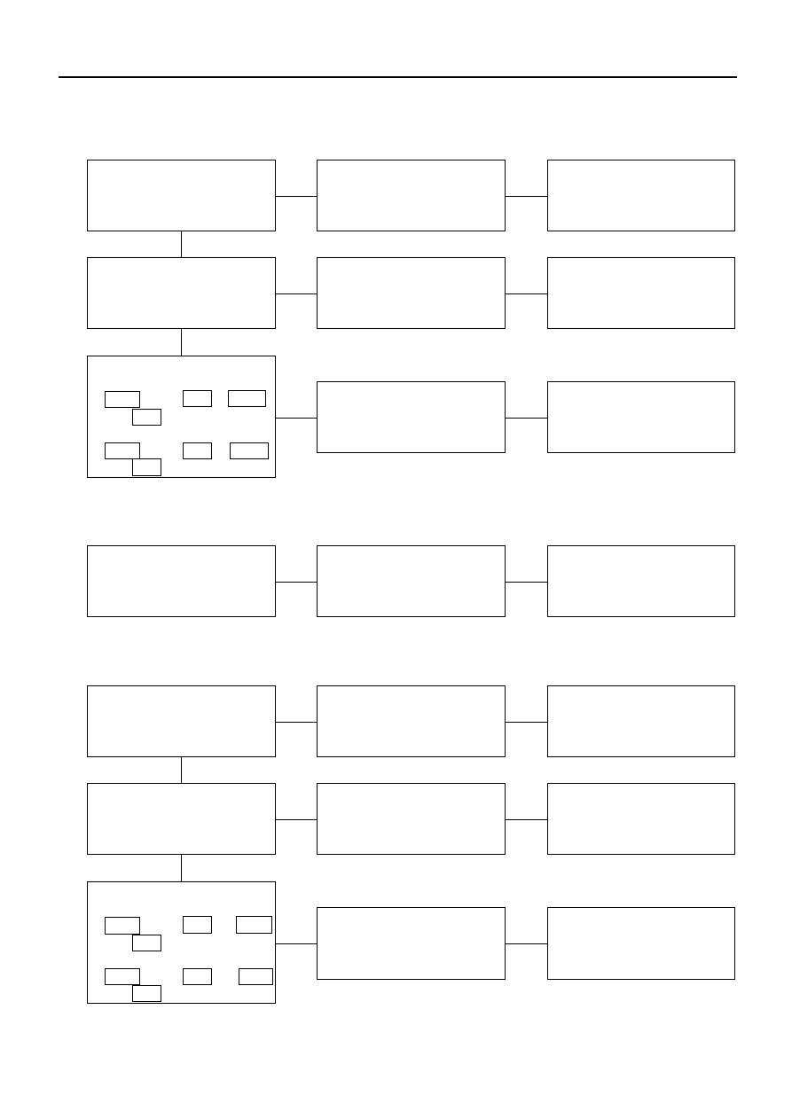
Mirror on the left (or right) side does not operate

Checkpoint

Trouble Cause

Countermeasure

SW. malfunction

Replace the door mirror
control SW.

Door mirror control SW.
function

NG

OK

OK

Mirror malfunction on the
left (or right) side

Repair or replace the door
mirror

Mirror function on the left
(or right) side

NG

Open circuit or poor
connector contact

Repair open circuit or
connector contact

Continuity between
[LHD]
1  B-26  and 2  D-2  (1  B-26
and 2  D-7 )
[RHD]
1  B-26  and 2  D-7  (1  B-26
and 2  D-2 )

NG

3.

Mirrors on the both sides operate only in the vertical (or horizontal) direction

SW. malfunction

Replace the door mirror
control SW.

Door mirror control SW.
function

NG

4.

Mirror on th left side operates only in the vertical (or horizontal) direction

SW. malfunction

Replace the door mirror
control SW.

Door mirror control SW.
function

NG

OK

OK

Door mirror malfunction

Repair or replace the door
mirror

Door mirror function

NG

Open circuit or poor
connector contact

Repair open circuit or
connector contact

Continuity between
[LHD]
8  B-26  and 3  D-2  (10  B-26
and 1  D-2 )
[RHD]
8  B-26  and 3  D-7  (10  B-26
and 1  D-7 )

NG

ELECTRICAL-BODY AND CHASSIS 8–313

5.

Mirror on the right side operates only in the vertical (or horizontal) direction

Checkpoint

Trouble Cause

Countermeasure

Door mirror control
malfunction

Replace the door mirror
control SW.

Door mirror control SW.
function

NG

OK

OK

Door mirror malfunction

Repair or replace the door
mirror

Door mirror function

NG

Open circuit or poor
connector contact

Repair open circuit or
connector contact

Continuity between
[LHD]
7  B-26  and 3  D-7  (5  B-26
and 1  D-7 )
[RHD]
7  B-26  and 3  D-2  (5  B-26
and 1  D-2 )

NG

8–314 ELECTRICAL-BODY AND CHASSIS

REMOVAL AND INSTALLATION

DOOR MIRROR CONTROL SWITCH

Removal

1. Instrument Panel Cluster Assembly

Refer to section 10 “BODY” for instrument panel
cluster assembly removal steps.

2. Door Mirror Control Switch

Disconnect the switch connector.

To remove the switch, push the lock from the back
side of the cluster assembly.

2. Door mirror control
     switch

1. Instrument panel
    cluster assembly

825RV094

Installation

To install, follow the removal steps in the reverse order.

DOOR MIRROR

Removal and Installation

Refer to the DOOR MIRROR in section 10 “BODY”.

ELECTRICAL-BODY AND CHASSIS 8–315

INSPECTION AND REPAIR

Door Mirror Control Switch

1. Switch Side Connector Circuit

Check continuity between the switch connector
terminals while operating the door mirror control
switch as shown in the following table.

1

2

5

6

7

8

9

10

3

4

Switch side

B-26

Connector No.

4

9

1

8

10

7

5

Switch position

(Up)

Door mirror (RH)

(Down)

(Left)

(Right)

(Up)

Door mirror (LH)

(Down)

(Left)

(Right)

2. Harness Side Connector Circuit

Remove the connector No. B-26 of the mirror
control switch and check voltage and continuity of
the harness side connector.

When there is no continuity at the terminal No. 5,
7, 8 and 10, it is considered that the circuit with
terminal No. 1 (B/W) is defective.

10

9

8

7

6

5

4

3

2

1

Harness side

B-26

▲ ▲

▲▲

▲▲

▲ ▲

▲▲

▲▲


Content   ..  1346  1347  1348  1349   ..