Isuzu D-Max / Isuzu Rodeo (TFR/TFS). Manual - part 1333


  Index      Ford     Isuzu D-Max / Isuzu Rodeo TFR/TFS series - service repair manual 1997-2003 year


Search            


Content   ..  1331  1332  1333  1334   ..


Isuzu D-Max / Isuzu Rodeo (TFR/TFS). Manual - part 1333


8–252 ELECTRICAL-BODY AND CHASSIS

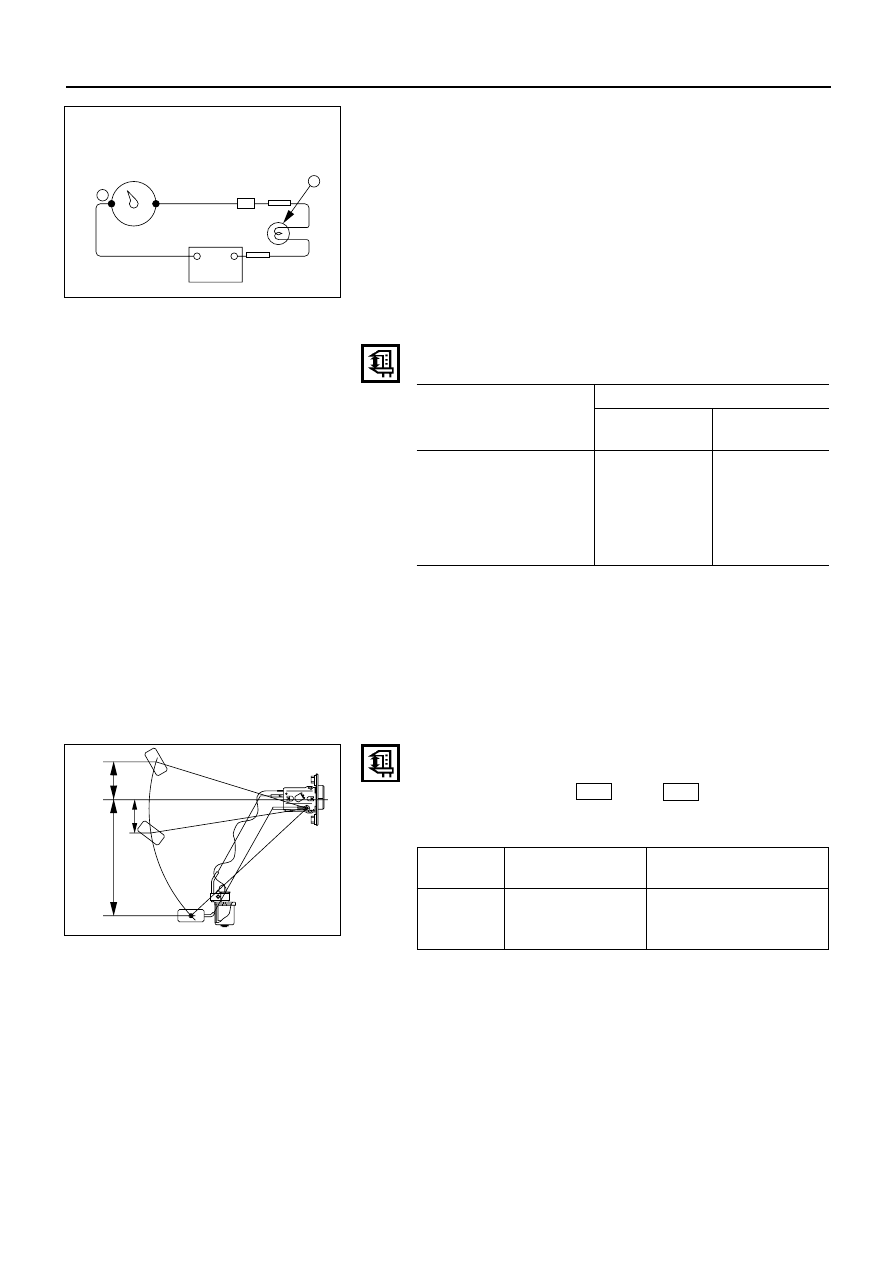
Fuel Tank Unit Inspection

Measure the fuel tank unit resistance between the
connector terminals 1  F-1 and 3  F-1 while shifting the
float from “E” to “F” point.

Fuel Tank Resistance

A

1/2

F

B

C

E

Base 
line

140RV003

Fuel Gauge Off-Vehicle Inspection

Use a circuit tester to measure the fuel gauge resistance.

Fuel Gauge Resistance

Standard

Measuring Point

With

Without

Tachometer

Tachometer

IGN (+) – Ground

223

110

IGN (+) – 7V

(0)

IGN (+) – UNIT

83

25

Ground – 7V

110

Ground – UNIT

140

135

7V – UNIT

25

Level

Float position

Standard resistance

mm

F (B)

51.7

17 ± 2.1

1/2 (A)

49.4

45 ± 4.5

E (C)

166.9

120 ± 6.5

1

W/O Tachometer

Unit

IGN 

140RV007

ELECTRICAL-BODY AND CHASSIS 8–253

Low Fuel Indicator Light Inspection

1. Disconnect the fuel tank unit wire connector.

2. Connect between terminal (YL) and (B).

3. Turn the key switch on.  Check that the bulb lights.

If operation is not correct, remove and check the bulb or
circuit.

2

B

YR

YL

1

140RV004

140RV010

Check level sensor operation

1. Remove the fuel tank unit.

2. Apply battery voltage between terminal (YL) and (B)

through a 3.4 watt bulb.  Check that the bulb lights.

Note:
It will take a short time for the bulb light.

3. Submerge the sensor in fuel.  Check that the bulb

goes out.

If operation is not correct, replace the fuel tank unit.

B

YL

Sensor

3.4 watt.

BRAKE SYSTEM WARNING LIGHT

The brake system warning light comes on while the
parking brake is set and the starter key is ON position.

Note:
The parking brake indicator light circuit is designed to
prevent driving of the vehicle with the parking brake on.
It does not indicate the condition of the parking brake
system.

The parking brake switch is in parallel with the brake fluid
switch.

This illustration is based on the floor type 
parking brake lever

Parking brake lever

Parking brake switch

825RV066

The brake system warning light also comes on when
reservoir brake fluid level falls below the specified limit
with the parking brake released and the starter switch is
ON position.

Level mark

Max

Min

Max

Min

330RV001

8–254 ELECTRICAL-BODY AND CHASSIS

VEHICLE SPEED SENSOR (INCORPORATED IN
THE SPEEDOMETER)

Vehicle Speed Sensor Inspection

Remove the speedometer from the meter assembly and
measure the resistance value between the terminals.

Speed Sensor Resistance

Note: Use the analog type circuit tester.

SEN

4P

IGN

GND

825RV064

Tester 

terminal

Red (+)

Black (–) Black (–)

Red (+)

Terminal 
symbol

4P – GND

4P

GND

4P

GND

13.5 – 16.5k

VEHICLE SPEED SENSOR (INSTALLED ON THE
TRANSMISSION)

The speed sensor is installed on the rear portion of the
transmission.

The number of pulses generated is four pulses per one
rotation of the pinion shaft.

Speed sensor

MSG T/M

(4

×2)

Speed sensor

MSG T/M

(4

×4)

826RV018

Speed sensor

MUA T/M

826RV044

ELECTRICAL-BODY AND CHASSIS 8–255

Vehicle Speed Sensor Inspection

1. Connect the vehicle speed sensor connector 1 M-10

0

(Diesel engine: 1  E-44  ) to the battery (+) terminal
and 2 M-10

0

(Diesel engine: 2 E-44  ) to the (–)

terminal.

2. Connect a resistance of 1.3K ohm to 5K ohm (1/4 W

or more) between connectors 1 M-10 (Diesel engine:
1  E-44 

0

) and 3 M-10  (Diesel engine: 3  E-44  )

CAUTION:
Be extremely careful not to connect the battery (+)
terminal to the connector 3 M-10 (Diesel engine: 
3  E-44  ).

This may damage the vehicle speed sensor.

3. Rotate the shaft of the vehicle speed sensor slowly

and measure the voltage at the both ends with a
digital tester.

The voltage, with one rotation of shaft fluctuates four
times in the following range: 10 to 14V — 2V or less.

+

1

2

3

Battery

820RV001


Content   ..  1331  1332  1333  1334   ..