Isuzu D-Max / Isuzu Rodeo (TFR/TFS). Manual - part 1308


  Index      Ford     Isuzu D-Max / Isuzu Rodeo TFR/TFS series - service repair manual 1997-2003 year


Search            


Content   ..  1306  1307  1308  1309   ..


Isuzu D-Max / Isuzu Rodeo (TFR/TFS). Manual - part 1308


8–152 ELECTRICAL-BODY AND CHASSIS

BACKUP LIGHT

1.

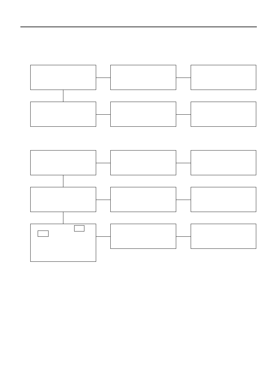
Backup light does not light on one side (RH or LH)

Checkpoint

Trouble Cause

Countermeasure

Burned out bulb or poor
connector contact

Replace the bulb or repair
connector contact

Backup light bulb continuity

Poor ground contact

Repair grounding point
contact

Grounding point

NG

OK

NG

2.

Backup light does not light on both sides

Poor fuse contact or blown
fuse

Reinstall or replace fuse
No. CB-11 (15A)

Fuse No. CB-11 (15A, Fuse
box)

Poor switch point contact
or faulty switch

Repair or replace the switch

Back up light switch (mode
switch) continuity

Open circuit or poor
connector contact

Repair open circuit or
connector contact

Voltage between 5  T-1  
(5  T-6  ) - ground with
starter switch ON and shift
lever into reverse position
(Should be battery voltage
present)

OK

OK

NG

NG

NG

ELECTRICAL-BODY AND CHASSIS 8–153

HORN

1.

Both sides of horn do not sound

Checkpoint

Trouble Cause

Countermeasure

Poor fuse contact or blown
fuse

Reinstall or replace fuse
No. EB-2 (10A)

Fuse No EB-2 (10A, Relay
and fuse box)

Poor ground contact

Repair the grounding point

Grounding point

Poor relay contact or faulty
horn relay

Reinstall or replace the
horn relay

Horn relay

Open circuit or poor
connector contact between
fuse No. EB-2 (10A) and
horn relay

Repair open circuit or
reconnect the connector

Voltage between connector
2  X-4 - ground or 5  X-4
- ground (Should be battery
voltage present)

Remove steering pad and
steering wheel

Poor switch point contact
or faulty switch

Repair or replace the horn
switch

Horn switch continuity

NG

OK

OK

OK

OK

NG

NG

NG

NG

Open circuit or poor
connector contact

Repair open circuit or
connector contact

Continuity between 

4 X-4 - 

12 C-42

1 X-4 - 

1 C-20 (1 C-21 )

OK

NG

8–154 ELECTRICAL-BODY AND CHASSIS

2.

One side of horn does not blow

Checkpoint

Trouble Cause

Countermeasure

Faulty horn assembly

Replace the horn assembly

Horn continuity between
connectors

Open circuit or poor
connector contact

Repair open circuit or
reconnect the connector

Voltage between 1 C-20  
(1 C-21  )- ground with
horn switch depressed
(Should be battery voltage
present)

NG

OK

NG

3.

Insufficient horn volume

Discharged battery

Recharge or replace the
battery

Battery condition

Stain or foreign material in
the horn

Clean and/or remove the
foreign material

Horn

OK

NG

NG

ELECTRICAL-BODY AND CHASSIS 8–155

REAR COMBINATION LIGHT

Stoplight

Removal

1. Open the rear gate.

2. Remove the screws of rear combination light.

3. Remove the rear combination light assembly.

D08RV751

4. Turn the bulb 

2 counterclockwise to remove it.

2

D08RV887

Installation

Follow the removal procedure in the reverse order to
install the rear combination light.

Pay close attention to the important points mentioned in
the following paragraphs.

Bulb

Be absolutely sure that each bulb is correctly installed.

This will prevent a poor contact and an open circuit.

REMOVAL AND INSTALLATION


Content   ..  1306  1307  1308  1309   ..