Content .. 1272 1273 1274 1275 ..
Isuzu D-Max / Isuzu Rodeo (TFR/TFS). Manual - part 1274
8–16 ELECTRICAL-BODY AND CHASSIS
BATTERY
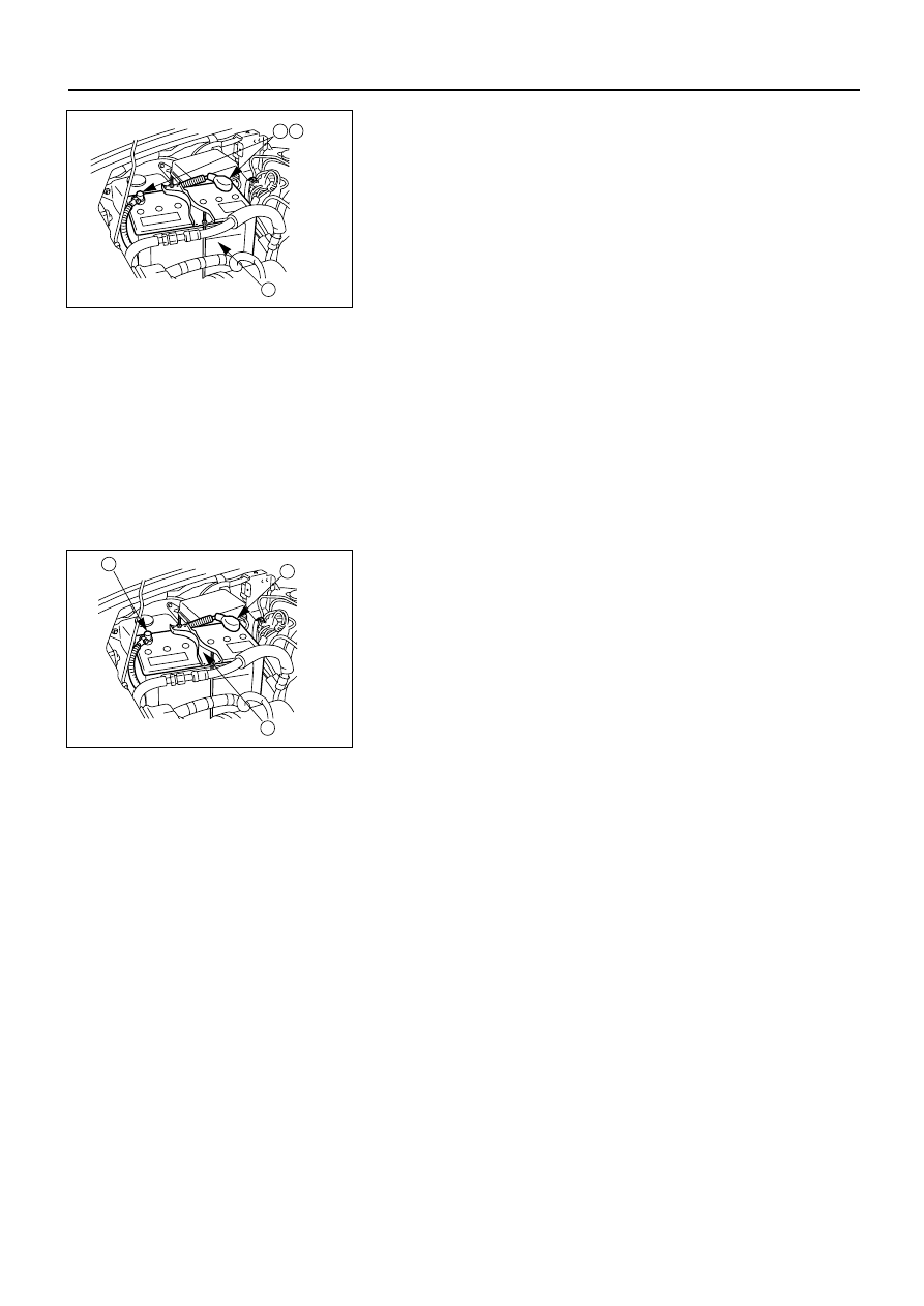
Inspection
1. Check the battery terminals 1 for corrosion.
2. Check the battery cables 2 for looseness.
3. Check the battery case 3 for cracks and other
damage.
4. Check the battery electrolyte level.
If the electrolyte level is excessively low, the battery
must be replaced.
5. If the battery has a built-in hydrometer, perform the
following steps:
1) Carefully clean the battery upper surface.
2) Check the hydrometer.
The hydrometer design will vary with the battery
manufacturer.
Refer to the illustration shown on the battery.
1 2
3
D08RV944
Battery Replacement
1. Disconnect the battery ground cable 1.
2. Disconnect the battery positive cable 2.
3. Remove the battery clamp 3.
4. Remove the battery
Caution:
It is important that the battery ground cable be removed
first.
Removing the battery positive cable first can result in a
short circuit.
1
2
3
D08RV945
Jump Starting the Engine with a Booster Battery
The following description assumes that you are using a
booster battery mounted on a second vehicle.
The listed steps (with some minor modifications) are also
applicable if you are using a naked booster battery or
special battery charging equipment.