Isuzu D-Max / Isuzu Rodeo (TFR/TFS). Manual - part 1249


  Index      Ford     Isuzu D-Max / Isuzu Rodeo TFR/TFS series - service repair manual 1997-2003 year


Search            


Content   ..  1247  1248  1249  1250   ..


Isuzu D-Max / Isuzu Rodeo (TFR/TFS). Manual - part 1249


ELECTRICAL-BODY AND CHASSIS  8-335 


  REMOVAL AND INSTALLATION 


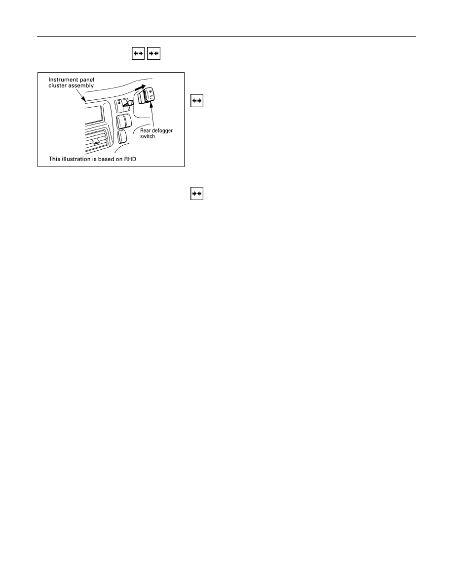
REAR DEFOGGER SWITCH (Except 

South Africa, Chile) 

Removal 

1.  Instrument Panel Cluster Assembly 

·  Refer to Section 10 “BODY” for instrument panel cluster

assembly removal steps. 

2.  Rear Defogger Switch 

·  Disconnect the switch connector. 
·  To remove the switch, push the lock from the back side

of the cluster assembly. 


Installation 

Follow the removal procedure in the reverse order to install the 
rear defogger switch. 


8-336  ELECTRICAL-BODY AND CHASSIS 

  INSPECTION AND REPAIR 


Switch side


REAR DEFOGGER SWITCH 

Rear Defogger Switch Connections 

Terminal No.

SW position

3

5

4

6

2

ON

OFF


REAR DEFOGGER RELAY 

Check continuity between the relay terminals. 

1

5

.........................No continuity 

(When battery voltage is applied between 

2

 and 

4

1

5

.........................Continuity 


INSPECTION OF REAR DEFOGGER HEAT 

WIRE 

·  Heat wires are printed on the inner side of glass. 
  To clean, use a soft cloth and wipe horizontally along the

wires. 

·  Never use glass cleaner or equivalent. 
·  When measuring voltage, wind a piece of tin foil around the

tip of the negative probe and press the foil against the wire
with your finger as shown. 


(1) Turn the ignition switch on. 
(2) Turn the defogger switch on. 
(3) Measure the voltage between the three points on the heat

wire and the (-) terminal with a voltmeter. 

(4) Check that the voltage becomes smaller from 

A

 to 

B

 to 

C

.


ELECTRICAL-BODY AND CHASSIS  8-337 


(5) If there is a place where the voltage suddenly changes to

0V, there is a broken wire between there and the power
side. 

(6) Move the tester probe from the position where the voltage

changes to 0V toward the power side and find where the
voltage suddenly increases. 


REPAIR OF BROKEN HEAT WIRE 

(1) Clean broken wire tips with white gasoline. 
(2) Place masking tape along both sides of wire to be repaired.


(3) Thoroughly mix the repair agent (Dupont paste No. 4817 or

equivalent). 

(4) Using a fine tip brush, apply a small amount to the wire. 
(5) After a couple of minutes, remove the masking tape. 
(6) Allow to stand at least 24 hours. 


8-338  ELECTRICAL-BODY AND CHASSIS 

RADIATOR LEVEL CONTROL WARNING SYSTEM 

PARTS LOCATION  


Content   ..  1247  1248  1249  1250   ..