Isuzu D-Max / Isuzu Rodeo (TFR/TFS). Manual - part 114
 

  Index      Ford     Isuzu D-Max / Isuzu Rodeo TFR/TFS series - service repair manual 1997-2003 year


Search            


Content   ..  112  113  114  115   ..


Isuzu D-Max / Isuzu Rodeo (TFR/TFS). Manual - part 114


6E–60

4JH1 ENGINE DRIVEABILITY AND EMISSIONS

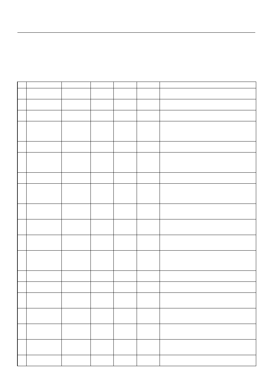
TYPICAL SCAN DATA & DEFINITIONS (ENGINE DATA)

Use the Typical Values Table only after the On-Board Diagnostic  System Check has been completed, no DTC(s) were
noted, and you have determined  that the on-board diagnostics are functioning properly. Tech 2 values from  a
properly-running engine may be used for comparison with the engine you are  diagnosing.
Condition : Vehicle stopping, engine running, air conditioning off & after warm-up (Coolant temperature approximately
80 deg.)

Tech 2 Parameter

Units

Idle

1500rpm

2000rpm

Description

1

Engine Speed

rpm

675 - 725

1475 - 1525

1975 - 2025

The engine speed is measured by ECM from the CKP
sensor.

2

Vehicle 

Speed

km/h

0

0

0

This displays vehicle speed. The vehicle speed is
measured by ECM from the vehicle speed sensor.

3

Pump Speed

rpm

335 - 375

725 - 775

975 - 1025

This displays injection pump speed. The injection speed
is measured by ECM from the pump cam sensor.

4

Accelerator
Position Signal 
Value of (  ) shows
A/T model

%

(0)

3 - 6 

(4 - 7)

5 - 8 

(8 - 11)

Throttle position operating angle is measured by the
ECM from throttle position output voltage. This should
display 0% at idle and 99 - 100% at full throttle. 

5

Idle Switch

Active/ Inactive

Active

Active

Inactive

This displays operating status of the idle switch. This
should display “Active” when the idle condition.

6

Mass Air Flow 
Sensor
Value of (  ) shows
A/T model

mg/strk

410 - 490 

(730 - 785)

380 - 450 

(700 - 780)

400 - 480 

(780 - 830)

This displays intake air amount. The mass air flow is
measured by ECM from the MAF sensor output voltage.

7

Barometric
Pressure

hpa

990 - 1015

990 - 1015

990 - 1015

The  barometric  pressure  is  measured  by  ECM  from  the
sensor in the ECM. This data is changing by altitude.

8

Desired Injection 
Quantity
Value of (  ) shows
A/T model

mg/stk

5 - 8 

(10 - 16)

5 - 9 

(8 - 12)

6 - 10 

(9 - 13)

This displays commanded value from the ECM. The ECM
compensates for fuel rate to basic rate.

9

Injection Quantity 
Value of (  ) shows
A/T model

mg/stk

6 - 8 

(10 - 16)

6 - 9 

(8 - 12)

7 - 10 

(9 - 13)

This displays actual fuel quantity. The PSG controls high
pressure solenoid valve to meet commanded value from
the ECM.

10

Desired Fuel 
Injection Start

°CA

1 - 3

2 - 4

3 - 6

This displays commanded value from the ECM. The ECM
compensates for fuel injection timing by throttle position
and various sensor signal.

11

Actual Injection 
Start

°CA

1 - 3

2 - 4

3 - 6

This  displays  actual  injection  timing  value  controlled  by
the TCV. The TCV controls duty ratio to meet
commanded value from the PSG.

12

Coolant
Temperature

°C

80 - 85

80 - 85

80 - 85

The ECT is measured by ECM from ECT sensor output
voltage. This data is changing by coolant temperature.
When the engine is normally warm upped, this data
displays approximately 80 deg.

13

Fuel Temperature

°C

25 - 50

25 - 50

25 - 50

The FT is measured by PSG from FT sensor. This data is
changing by fuel temperature.

14

Intake Air 
Temperature

°C

25 - 50

25 - 50

25 - 50

The  IAT  is  measured  by  ECM  from  IAT  sensor  output
voltage. This data is changing by intake air temperature.

15

Ignition Status

On12V/ Off0V

On 12V

On 12V

On 12V

This displays the key switch status indicated by the ECM
with key switch signal. This should display “Off 0V” at key
OFF and “On12V” at key ON.

16

Brake Switch 1

Active/ Inactive

Inactive

Inactive

Inactive

This displays operating status of the brake switch 1. This
should display “Active” when the brake pedal is stepped
on. 

17

Brake Switch 2

Active/ Inactive

Inactive

Inactive

Inactive

This displays operating status of the brake switch 2. This
should display “Active” when the brake pedal is stepped
on.

18

Clutch Switch 
Value of (  ) shows
A/T model

Active/ Inactive

Inactive 

( - )

Inactive 

( - )

Inactive 

( - )

This displays operating status of the clutch switch. This
should display “Active” when the clutch pedal is stepped
on.

19

Neutral Switch

On/Off

On 

On 

On 

This displays operating status of the neutral switch. This
should display “On” when the gear position is neutral. 

4JH1 ENGINE DRIVEABILITY AND EMISSIONS

6E–61

20

A/C Information 
Switch

Active 12V/
Inactive 0V

Inactive 0V

Inactive 0V

Inactive 0V

This displays the air conditioner request signal. This
should display “Active 12V” when the air conditioner
switch is switched on.

21

Diagnostic
Request

Active 0V/ 
Inactive 12V

Inactive 

12V

Inactive 

12V

Inactive 

12V

This displays the diagnostic request signal. This should
display “Inactive 12V” when the Tech 2 is connected.

22

System Voltage

V

10 -14

10 -14

10 -14

This displays the system voltage measured by the ECM
at ignition feed.

23

Main Relay

Active/ Inactive

Active

Active

Active

This displays operating status for the ECM main relay.
This should display “Inactive” at key OFF and “Active” at
key ON.

24

Glow Time Relay

Active 0V/ 
Inactive12V

Inactive 

12V

Inactive 

12V

Inactive 

12V

This displays operating status for the glow relay. This
should display “Inactive 12V” when the engine is warm
upped.

25

Check Engine 
Lamp

On/Off

Off

Off

Off

This displays operating status for the Check Engine
Lamp. This should display “On” when the Check Engine
Lamp is turned on.

26

Glow Time Telltale 

On/Off

Off

Off

Off

This displays operating status for the glow indicator lamp.
This should display “On” when the glow lamp is turned
on.

27

Desired Engine 
Idle Speed

rpm

700

700

700

The desired engine idle speed that the ECM
commanding. The ECM compensates for various engine
loads based on engine coolant temperature.

28

Start of Delivery

°CA

18 - 22

20 - 25

22 - 26

This  displays  commanded  value  from  the  ECM  when
engine start. 

29

A/C Request 

Active 0V/  
Inactive 12V

Inactive 

12V

Inactive 

12V

Inactive 

12V

This displays operating status of the A/C compressor.
This should display “Active 0V” when the compressor
relay is operated. 

30

Immobiliser

Active/ Inactive

Inactive

Inactive

Inactive

This should display “Inactive” when the immobiliser is
normal.

31

Immobiliser Signal

Received/ Not 
Received

Not 

Received

Not 

Received

Not 

Received

This should display “Not Received” when the immobiliser
is not activated.

32

Immobiliser
Function
Programmed

Yes/No

Yes

Yes

Yes

This should display “Yes” when the immobiliser is
programmed.

Tech 2 Parameter

Units

Idle

1500rpm

2000rpm

Description

6E–62

4JH1 ENGINE DRIVEABILITY AND EMISSIONS

MISCELLANEOUS TEST

The state of each circuit can be tested by using
miscellaneous test menus. Especially when DTC cannot
be detected, a faulty circuit can be diagnosed by testing
each circuit by means of these menus.
Even DTC has been detected, the circuit tests using
these menus could help discriminate between a
mechanical trouble and an electrical trouble.
Connect Tech 2 and select “Powertrain”,  “4JH1-TC
Bosch” & “Miscellaneous Test”.

F0: Lamps
F0: Check Light
When the Tech 2 is operated, “Malfunction Indicator
Lamp (Check Engine Lamp)” is turned on or off.
The circuit is normal if the “Malfunction Indicator Lamp
(Check Engine Lamp)” in the instrument panel is turned
on or off in accordance with this operation.

F1: Glow Time Telltale Test
When the Tech 2 is operated, “Glow Indicator Lamp” is
turned on or off.
The circuit is normal if the “Glow Indicator Lamp” in the
instrument panel is turned on or off in accordance with
this operation.

F1: Relays
F0: Glow Time Relay Test
When the Tech 2 is operated, glow relay signal turns ON
or OFF.
The circuit is normal if glow system is activated/
deactivated in accordance with this operation when key
switch is turned ON.

F2: Engine Speed (RPM) Control
When the Tech 2 is operated, “Desired Idle Speed”
increases 50rpm-by-50rpm up to 1200rpm.
The circuit is normal if engine speed is changed in
accordance with this operation.

• Press “Increase” key. 

Then, Desired Idle speed increases 50rpm-by-50rpm
up to 1200rpm. Engine speed is also changed by this
operation.

• Press “Quit” Key.

Engine Speed (RPM) Control

Engine Speed 

850 RPM

Desired Idle Speed 

850 RPM

Injection Quantity 

7.5mg/strk 

4JH1 ENGINE DRIVEABILITY AND EMISSIONS

6E–63

Plotting Snapshot Graph

This test selects several necessary items from the data
list to plot graphs and makes data comparison on a long
term basis. It is an effective test particularly in emission
related evaluations.

For trouble diagnosis, you can collect graphic data
(snap shot) directly from the vehicle.
You can replay the snapshot data as needed. Therefore,
accurate diagnosis is possible, even though the vehicle
is not available.


Content   ..  112  113  114  115   ..