Isuzu D-Max / Isuzu Rodeo (TFR/TFS). Manual - part 78


  Index      Ford     Isuzu D-Max / Isuzu Rodeo TFR/TFS series - service repair manual 1997-2003 year


Search            


Content   ..  76  77  78  79   ..


Isuzu D-Max / Isuzu Rodeo (TFR/TFS). Manual - part 78


4JA1-TC/4JH1-TC ENGINE DRIVEABILITY AND EMISSIONS

6E–307

Diagnostic Trouble Code (DTC) P1625 (Symptom Code B) (Flash Code 76) ECM 

Main Relay Switched Off Too Late

Step

Action

Value(s)

Yes

No

1

Was the “On-Board Diagnostic (OBD) System Check”
performed?

Go to Step 2

Go to On Board 

Diagnostic 

(OBD) System 

Check

2

1. Connect the Tech 2. 

2. Review and record the failure information. 

3. Select “F0: Read DTC Infor As Stored By ECU” in

“F0: Diagnostic Trouble Codes”. 

Is the DTC P1625 (Symptom Code B) stored as
“Present Failure”?

Go to Step 3

Refer to 

Diagnostic Aids 

and Go to Step 

3

3

1. Using the Tech 2, ignition “On” and engine “Off”. 

2. Select  “F1: Clear DTC Information” in “F0:

Diagnostic Trouble Codes” with the Tech 2 and
clear the DTC information. 

3. Operate the vehicle and monitor the “F0: Read

DTC Infor As Stored By ECU” in the “F0:
Diagnostic Trouble Codes”. 

Was the DTC P1625 (Symptom Code B) stored in this
ignition cycle?

Go to Step 4

Refer to 

Diagnostic Aids

4

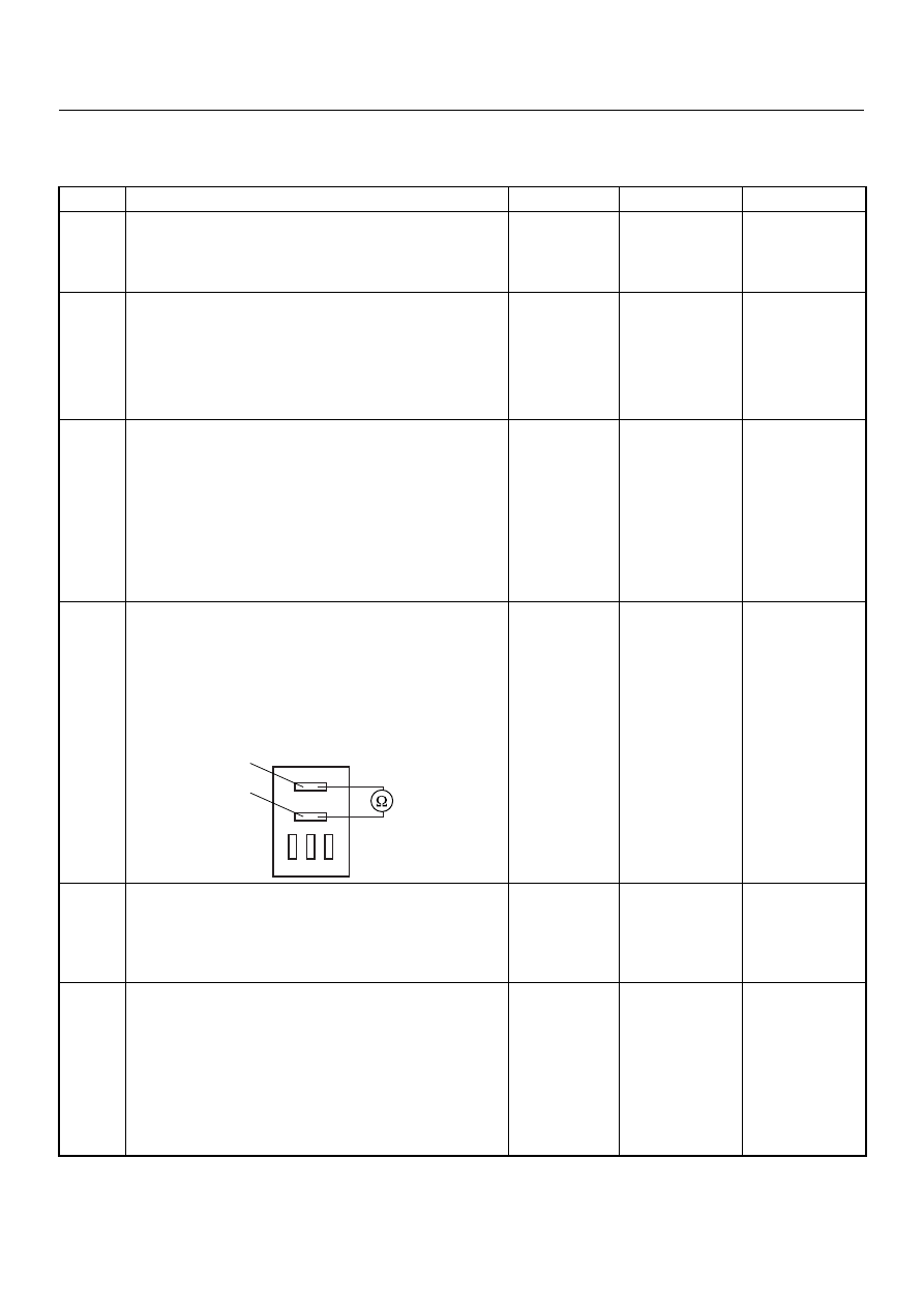
Using the DVM and check the ECM main relay. 

1. Ignition “Off”, engine “Off”. 

2. Remove the ECM main relay from the relay box. 

3. Check the relay switch. 

Was the DVM indicated specified value?

No continuitly

Go to Step 5

Replace ECM 

main relay and 

verify repair

5

Is the ECM programmed with the latest software
release? 
If not, download the latest software to the ECM using
the “SPS (Service Programming System)”. 
Was the problem solved?

Verify repair

Go to Step 6

6

Replace the ECM. 
Is the action complete? 
IMPORTANT: The replacement ECM must be
programmed. Refer to section of the Service
Programming System (SPS) in this manual. 
Following ECM programming, the immobiliser system
(if equipped) must be linked to the ECM. Refer to
section 11 “Immobiliser System-ECM replacement” for
the ECM/Immobiliser linking procedure.

Verify repair

1

2

ECM

Main Relay

6E–308

4JA1-TC/4JH1-TC ENGINE DRIVEABILITY AND EMISSIONS

DIAGNOSTIC TROUBLE CODE (DTC) P1630 (SYMPTOM CODE A) 

(FLASH CODE 51) FUEL INJECTION QUANTITY CIRCUIT MALFUNCTION

DIAGNOSTIC TROUBLE CODE (DTC) P1630 (SYMPTOM CODE B) 

(FLASH CODE 51) FUEL INJECTION QUANTITY CIRCUIT MALFUNCTION

Condition for setting the DTC and action taken when the DTC sets

Circuit Description

The ECM is calculates an injection quantity and an
injection timing using the various sensors. And the PSG
controls the high pressure solenoid valve depending on

programmed pump map data.

Flash 

Code

Code

Symptom 

Code

MIL

DTC Name

DTC Setting Condition

Fail-Safe (Back Up)

51

P1630

A

ON

Fuel Injection Quantity Circuit 
Malfunction

The PSG (pump control unit) 
detects high pressure sole-
noid valve control circuit mal-
function due to high current.

Fuel injection quantity is 
reduced.

B

ON

Fuel Injection Quantity Circuit 
Malfunction

The PSG (pump control unit) 
detects high pressure sole-
noid valve control circuit mal-
function due to continuous 
current.

1. MAB (fuel cutoff solenoid 

valve) is operated. 

2. Desired injection quantity 

becomes 0mg/strk.

45

16 15 14 13 12 11 10 9

8 7 6 5 4 3 2 1

Battery
Voltage

Battery
Voltage

0.5
RED/
YEL

2.0
BLU/
RED

7

PSG(Pump Control Unit)

Injection
Pump

2

1

5

8

0.5
WHT

2.0
BLU/
RED

0.5
BLU/
BLK

0.5
RED

0.5
ORG

100

3

58

99

105

91

0.5
PNK

6

2.0
BLK

µP

CAN
Controller

Batt

Batt

IC

µP

0.5
BLU

Stop
Light
10A

1.25
BLK

µP

Engine
Control
Module
(ECM)

ECM
Main Relay

4JA1-TC/4JH1-TC ENGINE DRIVEABILITY AND EMISSIONS

6E–309

Diagnostic Aids

An intermittent may be caused by the following:

• Poor connections.

• Misrouted harness.

• Rubbed through wire insulation.

• Broken wire inside the insulation.
Check for the following conditions:

• Poor connection at ECM and PSG-Inspect harness

connectors for backed out terminals, improper
mating, broken locks, improperly formed or damaged
terminals, and poor terminal to wire connection.

Diagnostic Trouble Code (DTC) P1630 (Symptom Code A) (Flash Code 51) Fuel 

Injection Quantity Circuit Malfunction

Diagnostic Trouble Code (DTC) P1630 (Symptom Code B) (Flash Code 51) Fuel 

Injection Quantity Circuit Malfunction

Step

Action

Value(s)

Yes

No

1

Was the “On-Board Diagnostic (OBD) System Check”
performed?

Go to Step 2

Go to On Board 

Diagnostic 

(OBD) System 

Check

2

1. Connect the Tech 2. 

2. Review and record the failure information. 

3. Select “F0: Read DTC Infor As Stored By ECU” in

“F0: Diagnostic Trouble Codes”. 

Is the DTC P1630 (Symptom Code A) or P1630
(symptom Code B) stored as “Present Failure”?

Go to Step 3

Refer to 

Diagnostic Aids 

and Go to Step 

3

3

1. Using the Tech 2, ignition “On” and engine “Off”. 

2. Select  “F1: Clear DTC Information” in “F0:

Diagnostic Trouble Codes” with the Tech 2 and
clear the DTC information. 

3. Operate the vehicle and monitor the “F0: Read

DTC Infor As Stored By ECU” in the “F0:
Diagnostic Trouble Codes”. 

Was the DTC P1630 (Symptom Code A) or P1630
(symptom Code B) stored in this ignition cycle?

Go to Step 4

Refer to 

Diagnostic Aids

4

Replace the injection pump assembly. 
Is the action complete?

Verify repair

6E–310

4JA1-TC/4JH1-TC ENGINE DRIVEABILITY AND EMISSIONS

DIAGNOSTIC TROUBLE CODE (DTC) P1650 (SYMPTOM CODE A) 

(FLASH CODE 44) CAN DEVICE OFFLINE

DIAGNOSTIC TROUBLE CODE (DTC) P1650 (SYMPTOM CODE B) 

(FLASH CODE 44) CAN DEVICE HANG-UP

Condition for setting the DTC and action taken when the DTC sets

Circuit Description

The interchange of data between the engine control
module (ECM) and the pump control unit (PSG) is
performed via a CAN-bus system. The individual CAN-
bus systems are connected via two interfaces and can
exchange information and data. This allows control
modules that are connected to different CAN-bus
systems to communicate. 

Diagnostic Aids

An intermittent may be caused by the following:

• Poor connections.

• Misrouted harness.

• Rubbed through wire insulation.

• Broken wire inside the insulation.
Check for the following conditions:

Flash 

Code

Code

Symptom 

Code

MIL

DTC Name

DTC Setting Condition

Fail-Safe (Back Up)

44

P1650

A

ON

CAN Device Offline

CAN controller detects Bus-
off or canceling.

MAB (fuel cutoff solenoid 
valve) is operated. 

B

ON

CAN Device Hang-up

CAN controller does not react 
under engine running.

45

16 15 14 13 12 11 10 9

8 7 6 5 4 3 2 1

Battery
Voltage

Battery
Voltage

0.5
RED/
YEL

2.0
BLU/
RED

7

PSG(Pump Control Unit)

Injection
Pump

2

1

5

8

0.5
WHT

2.0
BLU/
RED

0.5
BLU/
BLK

0.5
RED

0.5
ORG

100

3

58

99

105

91

0.5
PNK

6

2.0
BLK

µP

CAN
Controller

Batt

Batt

IC

µP

0.5
BLU

Stop
Light
10A

1.25
BLK

µP

Engine
Control
Module
(ECM)

ECM
Main Relay


Content   ..  76  77  78  79   ..