Isuzu D-Max / Isuzu Rodeo (TFR/TFS). Manual - part 70
4JA1-TC/4JH1-TC ENGINE DRIVEABILITY AND EMISSIONS
6E–275
8
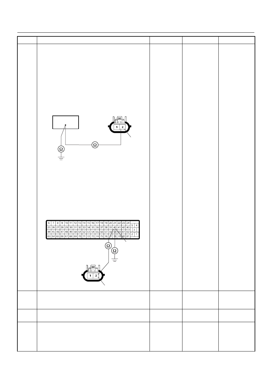
Using the DVM and check the exhaust throttle VSV 1
circuit.
Breaker box is available:
1. Ignition “Off”, engine “Off”.
2. Install the breaker box as type A. (ECM
disconnected) Ref. Page 6E-81
3. Remove the exhaust throttle VSV 1 connector.
4. Check the circuit for open or short to ground
circuit.
Was the problem found?
Breaker box is not available:
1. Ignition “Off”, engine “Off”.
2. Disconnect the ECM connector.
3. Remove the exhaust throttle VSV 1 connector.
4. Check the circuit for open or short to ground
circuit.
Was the problem found?
—
Repair faulty
harness and
verify repair
Go to Step 11
9
Substitute a known good exhaust throttle VSV 1 and
recheck.
Was the problem solved?
—
Go to Step 10
Go to Step 11
10
Replace the exhaust throttle VSV 1.
Is the action complete?
—
Verify repair
—
11
Is the ECM programmed with the latest software
release?
If not, download the latest software to the ECM using
the “SPS (Service Programming System)”.
Was the problem solved?
—
Verify repair
Go to Step 12
Step
Action
Value(s)
Yes
No
2
40
C-13
2
40
C-13
C-56