Isuzu D-Max / Isuzu Rodeo (TFR/TFS). Manual - part 69


  Index      Ford     Isuzu D-Max / Isuzu Rodeo TFR/TFS series - service repair manual 1997-2003 year


Search            


Content   ..  67  68  69  70   ..


Isuzu D-Max / Isuzu Rodeo (TFR/TFS). Manual - part 69


4JA1-TC/4JH1-TC ENGINE DRIVEABILITY AND EMISSIONS

6E–271

10

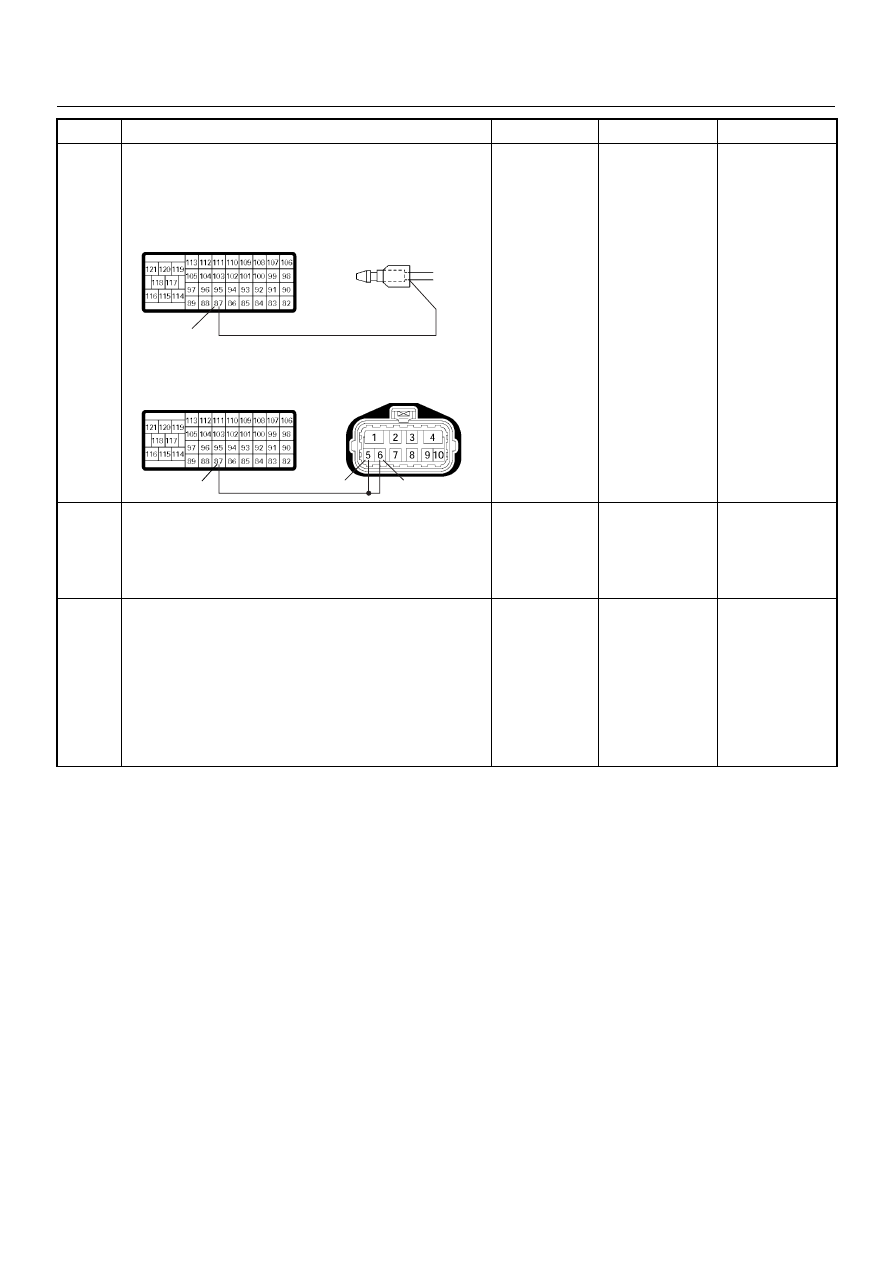
Repair the open circuit between the neutral switch
connector (inhibitor switch connector) and ECM. 
Is the action complete?

Verify repair

11

Is the ECM programmed with the latest software
release? 
If not, download the latest software to the ECM using
the “SPS (Service Programming System)”. 
Was the problem solved?

Verify repair

Go to Step 12

12

Replace the ECM. 
Is the action complete? 
IMPORTANT: The replacement ECM must be
programmed. Refer to section of the Service
Programming System (SPS) in this manual. 
Following ECM programming, the immobiliser system
(if equipped) must be linked to the ECM. Refer to
section 11 “Immobiliser System-ECM replacement” for
the ECM/Immobiliser linking procedure.

Verify repair

Step

Action

Value(s)

Yes

No

87

87

6

5

C-57

C-57

M/T

A/T

E-12

E-51

6E–272

4JA1-TC/4JH1-TC ENGINE DRIVEABILITY AND EMISSIONS

DIAGNOSTIC TROUBLE CODE (DTC) P1576 (SYMPTOM CODE 4) (FLASH 

CODE 71) EXHAUST THROTTLE VSV 1 CIRCUIT VOLTAGE LOW

DIAGNOSTIC TROUBLE CODE (DTC) P1576 (SYMPTOM CODE 8) (FLASH 

CODE 71) EXHAUST THROTTLE VSV 1 CIRCUIT VOLTAGE HIGH

Condition for setting the DTC and action taken when the DTC sets

Circuit Description

The switch engine warming signals the engine control
module (ECM) to activate the quick warm-up system
(QWS). 
Switch only provides the request and that the ECM
decides when to activated when certain conditions are
met.

If the exhaust throttle VSV 1 circuit is open or short
ground circuit, DTC P1576 (Symptom Code 4) is stored.
If the exhaust throttle VSV 1 circuit is short to voltage
circuit, DTC P1576 (Symptom Code 8) is stored.

Flash 

Code

Code

Symptom 

Code

MIL

DTC Name

DTC Setting Condition

Fail-Safe (Back Up)

71

P1576

4

ON

Exhaust Throttle VSV 1 Cir-
cuit Voltage Low

Exhaust throttle VSV 1 circuit 
open or short to ground cir-
cuit.

No fail-safe function.

8

ON

Exhaust Throttle VSV 1 Cir-
cuit Voltage High

Exhaust throttle VSV 1 circuit 
short to voltage circuit.

Batt

µP

Batt

µP

Batt

µP

0.5
BLK/
URG

0.5
BRN/
RED

0.5
BLU/
RED

0.5
BLU/
RED

4JA1-TC

0.5
GRY/
YEL

97

46

61

0.5
WHT/
RED

83

0.5
GRN/
RED

88

0.5
BLK/
RED

92

0.5
BLK/
BLU

84

IAT
Sensor

MAF &
IAT
Sensor

Rr Fog
Light
10A

EGR-
EVRV

0.5
WHT/
BLK

0.5
BLU/
RED

0.5
WHT/
BLU

0.5
BLU/
RED

0.5
GRN/
RED

0.5
BLU/
RED

Exhaust
Throttle
VSV2

Exhaust
Throttle
VSV1

Engine
Warming Up
SW

Thermo
SW

2

4

5

3

1

Battery
Voltage

ECM
Main Relay

IC

IC

IC

CPU

Engine
Control
Module
(ECM)

40

4JA1-TC/4JH1-TC ENGINE DRIVEABILITY AND EMISSIONS

6E–273

Diagnostic Aids

An intermittent may be caused by the following:

• Poor connections.

• Misrouted harness.

• Rubbed through wire insulation.

• Broken wire inside the insulation.
Check for the following conditions:

• Poor connection at ECM-Inspect harness connectors

for backed out terminals, improper mating, broken
locks, improperly formed or damaged terminals, and
poor terminal to wire connection.

• Damaged harness-Inspect the wiring harness for

damage. If the harness appears to be OK, observe
the DTC P1576 display on the Tech2 while moving
connectors and wiring harnesses. 

Diagnostic Trouble Code (DTC) P1576 (Symptom Code 4) (Flash Code 71) 

Exhaust Throttle VSV 1 Circuit Voltage Low

Step

Action

Value(s)

Yes

No

1

Was the “On-Board Diagnostic (OBD) System Check”
performed?

Go to Step 2

Go to On Board 

Diagnostic 

(OBD) System 

Check

2

1. Connect the Tech 2. 

2. Review and record the failure information. 

3. Select “F0: Read DTC Infor As Stored By ECU” in

“F0: Diagnostic Trouble Codes”. 

Is the DTC P1576 (Symptom Code 4) stored as
“Present Failure”?

Go to Step 3

Refer to 

Diagnostic Aids 

and Go to Step 

3

3

1. Using the Tech 2, ignition “On” and engine “Off”. 

2. Select  “F1: Clear DTC Information” in “F0:

Diagnostic Trouble Codes” with the Tech 2 and
clear the DTC information. 

3. Operate the vehicle and monitor the “F0: Read

DTC Infor As Stored By ECU” in the “F0:
Diagnostic Trouble Codes”. 

Was the DTC P1576 (Symptom Code 4) stored in this
ignition cycle?

Go to Step 4

Refer to 

Diagnostic Aids 

and Go to Step 

4

4

Check for poor/faulty connection at the exhaust
throttle VSV 1 or ECM connector. If a poor/faulty
connection is found, repair as necessary. 
Was the problem found?

Verify repair

Go to Step 5

40

C-56

C-13

6E–274

4JA1-TC/4JH1-TC ENGINE DRIVEABILITY AND EMISSIONS

5

Using the DVM and check the exhaust throttle VSV 1.

1. Ignition “Off”,  engine “Off”. 

2. Disconnect the exhaust throttle VSV 1 connector. 

3. Measure the resistance of exhaust throttle VSV 1

solenoid coil. 

Does the tester indicate standard resistance?   

Approximately 

40

Ω at 20°C

Go  to  Step 6

Go to Step 9

6

Using the DVM and check the exhaust throttle VSV 1
power supply circuit. 

1. Ignition “On”, engine “Off”. 

2. Remove the exhaust throttle VSV 1 connector. 

3. Check the circuit for open circuit. 

Was the DVM indicated specified value?

Battery 
voltage

Go to Step 8

Go to Step 7

7

Repair the open circuit between the ECM main relay
and exhaust throttle VSV 1. 
Is the action complete?

Verify repair

Step

Action

Value(s)

Yes

No

1

2

1

2

VSV-1

V

1

C-13

1

1

C-13

X-4


Content   ..  67  68  69  70   ..