Infiniti QX4 (R50). Manual - part 32
SAT649I
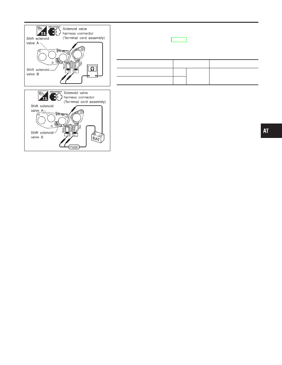
Component Inspection
=NBAT0041
SHIFT SOLENOID VALVE A AND B
NBAT0041S01
I
For removal, refer to AT-273.
Resistance Check
NBAT0041S0101
I
Check resistance between terminals (3 or 2) and ground.
Solenoid valve
Terminal No.
Resistance (Approx.)
Shift solenoid valve A
3
Ground
20 - 40
Ω
Shift solenoid valve B
2
SAT648I
Operation Check
NBAT0041S0102
I
Check solenoid valve by listening for its operating sound while
applying battery voltage to the terminals (3 or 2) and ground.
GI
MA
EM
LC
EC
FE
TF
PD
AX
SU
BR
ST
RS
BT
HA
SC
EL
IDX
DTC P0731 IMPROPER SHIFTING TO 1ST GEAR POSITION
Component Inspection
AT-125