Infiniti G35 (V35). Manual - part 693


  Index      Infiniti     Infiniti G35 (V35) Coupe - service repair manual 2007 year


Search            


Content   ..  691  692  693  694   ..


Infiniti G35 (V35). Manual - part 693


RF-28

SUNROOF

3.

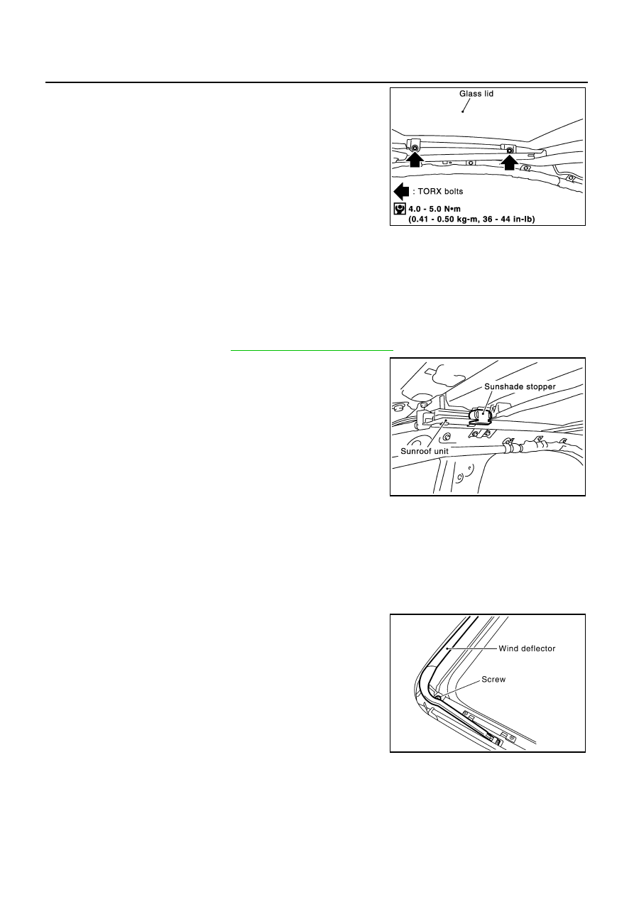
Remove TORX bolts (T25) and then detach glass lid.

Installation

1.

Tighten bolts diagonally on the glass lid.

2.

After installation, carry out fitting adjustment.

SUNSHADE
Removal

NOTE:
Removing is possible even by the on vehicle.
1.

Remove the headlining. Refer to 

EI-36, "Removal and Installation"

 .

2.

Remove sunshade stopper.

3.

Pull sunshade to the rear end of the sunroof frame, then remove
it from the sunroof frame.

CAUTION:

Thing working to damage neither sunshade and sunshade
knob while lifting up a little.

Installation

Install in the reverse order of removal.

WIND DEFLECTOR
Removal

NOTE:
Removing is possible even by the on vehicle.

1.

Sunroof lid is fully open.

2.

Remove spring hinge screws and then remove hinge from the
frame.

3.

Remove the stopper from the sunroof unit assembly.

4.

Turn the wind deflector and then remove it from ditch of the sun-
roof unit assembly.

Installation

Install in the reverse order of removal.

PIIA3508E

PIIA3506E

PIIA3510E

SUNROOF

RF-29

C

D

E

F

G

H

J

K

L

M

A

B

RF

SUNROOF MOTOR ASSEMBLY
Removal

1.

Remove headlining. Refer to 

EI-36, "Removal and Installation"

 .

2.

Remove sunroof motor mounting screw.

3.

Disconnect harness connector from sunroof motor, then remove
sunroof motor assembly.

CAUTION:

When removing the sunroof motor assembly, be sure that
the sunroof is in the fully open position.

Do not run the removed sunroof motor assembly as a
single unit.

Installation

Move the sunroof motor assembly laterally little by little so that the gear is completely engaged into the wire on
the sunroof unit assembly and the mounting surface becomes parallel. Tighten the sunroof   motor assembly
with screws.

CAUTION:

Before installing the sunroof motor assembly, be sure to place the link and wire assembly in the
symmetrical and fully closed position.

Initialization of it after installing the sunroof motor. Refer to 

RF-11, "INITIALIZATION PROCEDURE"

.

PIIA3502E

RF-30

SUNROOF

RFD-1

REAR FINAL DRIVE

D  DRIVELINE/AXLE

CONTENTS

C

E

F

G

H

I

J

K

L

M

SECTION 

A

B

RFD

REAR FINAL DRIVE

PRECAUTIONS .......................................................... 2

Service Notice or Precautions  .................................. 2

PREPARATION ........................................................... 3

Special Service Tools  ............................................... 3
Commercial Service Tools ........................................ 6

NOISE, VIBRATION AND HARSHNESS (NVH) 
TROUBLESHOOTING ................................................ 7

NVH Troubleshooting Chart  ..................................... 7

DESCRIPTION ............................................................ 8

Cross-Sectional View  ............................................... 8

DIFFERENTIAL GEAR OIL  ........................................ 9

Changing Differential Gear Oil  ................................. 9

DRAINING ............................................................. 9
FILLING ................................................................. 9

Checking Differential Gear Oil .................................. 9

OIL LEAKAGE AND OIL LEVEL  ........................... 9

FRONT OIL SEAL  .................................................... 10

Removal and Installation  ........................................ 10

IDENTIFICATION STAMP OF REPLACEMENT 
FREQUENCY OF FRONT OIL SEAL  ................. 10
REMOVAL ............................................................11
INSTALLATION ................................................... 12

SIDE OIL SEAL  ........................................................ 15

Removal and Installation  ........................................ 15

REMOVAL ........................................................... 15
INSTALLATION ................................................... 15

REAR FINAL DRIVE ASSEMBLY  ............................ 17

Removal and Installation  ........................................ 17

COMPONENTS ................................................... 17
REMOVAL ........................................................... 17
INSTALLATION ................................................... 18

Disassembly and Assembly (R200 2-Pinion)  ......... 19

COMPONENTS ................................................... 19
ASSEMBLY INSPECTION AND ADJUSTMENT ... 20
DISASSEMBLY ................................................... 24
INSPECTION AFTER DISASSEMBLY ................ 28
ADJUSTMENT AND SELECTION OF ADJUST-
ING WASHERS  ................................................... 28
ASSEMBLY ......................................................... 33

Disassembly and Assembly (R200V LSD)  ............. 39

COMPONENTS ................................................... 39
ASSEMBLY INSPECTION AND ADJUSTMENT ... 40
DISASSEMBLY ................................................... 44
INSPECTION AFTER DISASSEMBLY ................ 48
ADJUSTMENT AND SELECTION OF ADJUST-
ING WASHERS  ................................................... 48
ASSEMBLY ......................................................... 53

SERVICE DATA AND SPECIFICATIONS (SDS)  ...... 59

General Specifications ............................................ 59
Inspection and Adjustment  ..................................... 59

DRIVE GEAR RUNOUT  ...................................... 59
DIFFERENTIAL SIDE GEAR CLEARANCE  ....... 59
PRELOAD TORQUE  ........................................... 59
BACKLASH ......................................................... 59
COMPANION FLANGE RUNOUT ....................... 59
SELECTIVE PARTS  ............................................ 60


Content   ..  691  692  693  694   ..