Infiniti G35 (V35). Manual - part 592


  Index      Infiniti     Infiniti G35 (V35) Coupe - service repair manual 2007 year


Search            


Content   ..  590  591  592  593   ..


Infiniti G35 (V35). Manual - part 592


LT-48

DAYTIME LIGHT SYSTEM

CONSULT-II Functions (BCM)

NKS0027Q

Refer to 

LT-16, "CONSULT-II Functions (BCM)"

 .

CONSULT-II Functions (IPDM E/R)

NKS0027R

Refer to 

LT-18, "CONSULT-II Functions (IPDM E/R)"

 .

Daytime Light Control Does Not Operate Properly

NKS0027S

1. 

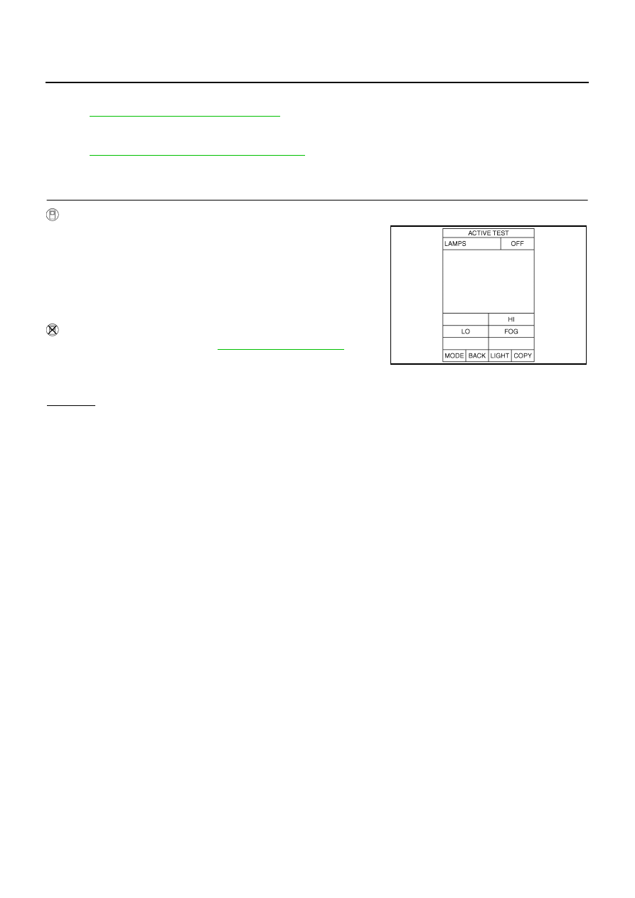
FRONT FOG LAMP ACTIVE TEST

With CONSULT-II

1.

Select “IPDM E/R” on CONSULT-II, and select “ACTIVE TEST”
on “SELECT DIAG MODE” screen.

2.

Select “LAMPS” on “SELECT TEST ITEM” screen. 

3.

Touch “FOG” screen.

4.

Make sure front fog lamp operates.

Without CONSULT-II

1.

Start auto active test. Refer to 

PG-21, "Auto Active Test"

 .

2.

Make sure front fog lamp operates.

OK or NG

OK

>> GO TO 5.

NG

>> GO TO 2.

Front fog lamp should operate.

Front fog lamp should operate.

SKIA5774E

DAYTIME LIGHT SYSTEM

LT-49

C

D

E

F

G

H

I

J

L

M

A

B

LT

2. 

CHECK FRONT FOG LAMP INPUT SIGNAL 

With CONSULT-II

1.

Turn ignition switch OFF.

2.

Disconnect front combination lamp RH and LH connectors.

3.

Select “IPDM E/R” on CONSULT-II, and select “ACTIVE TEST”
on “SELECT DIAG MODE” screen.

4.

Select “LAMPS” on “SELECT TEST ITEM” screen. 

5.

Touch “FOG” screen.

6.

When front fog lamp is operating, check voltage between front
combination lamp RH and LH harness connectors and ground.

Without CONSULT-II

1.

Turn ignition switch OFF.

2.

Disconnect front combination lamp RH and LH connectors.

3.

Start auto active test. Refer to 

PG-21, "Auto Active Test"

 . 

4.

When front fog lamp is operating, check voltage between front combination lamp RH and LH harness con-
nectors and ground.

OK or NG

OK

>> GO TO 4.

NG

>> GO TO 3.

3. 

CHECK FRONT FOG LAMP CIRCUIT 

1.

Turn ignition switch OFF.

2.

Disconnect IPDM E/R connector.

3.

Check continuity between IPDM E/R harness connector E8 ter-
minal 36 and front combination lamp RH harness connector E24
terminal 1.

4.

Check continuity between IPDM E/R harness connector E8 ter-
minal 37 and front combination lamp LH harness connector E41
terminal 1.

OK or NG

OK

>> Replace IPDM E/R.

NG

>> Repair harness or connector.

(+)

(

)

Voltage

Front combination 

lamp connector

Terminal

RH

E24

Ground Battery 

voltage

LH

E41

1

(+)

(

)

Voltage

Front combination 

lamp connector

Terminal

RH

E24

1

Ground Battery 

voltage

LH

E41

1

PKIA4889E

36 – 1

: Continuity should exist.

37 – 1

: Continuity should exist.

PKIA4890E

LT-50

DAYTIME LIGHT SYSTEM

4. 

CHECK FRONT FOG LAMP GROUND 

1.

Check continuity between front combination lamp RH harness
connector E24 terminal 8 and ground.

2.

Check continuity between front combination lamp LH harness
connector E41 terminal 8 and ground.

OK or NG

OK

>> Check front fog lamp bulbs.

NG

>> Repair harness or connector.

5. 

CHECK SELF-DIAGNOSIS

Select “BCM” on CONSULT-II, and self-diagnosis for “BCM”.

Displayed results of self-diagnosis

No 

malfunction 

detected>> Replace BCM. Refer to 

BCS-16,

"Removal and Installation of BCM"

 .

CAN communications or CAN system>> Check BCM CAN commu-

nication system. Refer to 

BCS-15, "CAN Communica-

tion Inspection Using CONSULT-II (Self-Diagnosis)"

 .

Aiming Adjustment

NKS0053U

Refer to 

LT-29, "Aiming Adjustment"

 .

Bulb Replacement

NKS0053V

Refer to 

LT-30, "Bulb Replacement"

 .

Removal and Installation

NKS0053W

Refer to 

LT-32, "Removal and Installation"

 .

8 – Ground

: Continuity should exist.

8 – Ground

: Continuity should exist.

PKIA4585E

PKIA7627E

AUTO LIGHT SYSTEM

LT-51

C

D

E

F

G

H

I

J

L

M

A

B

LT

AUTO LIGHT SYSTEM

PFP:28491

Component Parts and Harness Connector Location

NKS000GY

System Description

NKS000GZ

Automatically turns ON/OFF the parking lamps and the headlamps in accordance with ambient light.
Timing for when lamps turn ON/OFF can be selected using four modes.

OUTLINE

The auto light control system has an optical sensor inside it that detects outside brightness.
When the lighting switch is in AUTO position, it automatically turns ON/OFF the parking lamps and the head-
lamps in accordance with ambient light. Sensitivity can be adjusted in four steps. For the details of the setting,
Refer to 

LT-59, "SETTING CHANGE FUNCTIONS"

 .

Optical sensor, power is supplied

from BCM (body control module) terminal 17

to optical sensor terminal 1.

Optical sensor, ground is supplied

to optical sensor terminal 3

through BCM terminal 18.

When ignition switch is turn to ON position, and

PKIB6499E


Content   ..  590  591  592  593   ..