Infiniti G35 (V35). Manual - part 588
LT-32
HEADLAMP - XENON TYPE -
Removal and Installation
NKS002O2
REMOVAL
1.
Open the driver and front passenger window, and then discon-
nect the battery cable from the negative terminal or remove
power fuse.
CAUTION:
After battery cables are disconnected, never open/close the
driver and/or front passenger door with the window in the
full up position. The automatic window adjusting function
will not work and the side roof panel may be damaged.
2.
Remove front grille. Refer to
3.
Remove front undercover and fender protector. Refer to
.
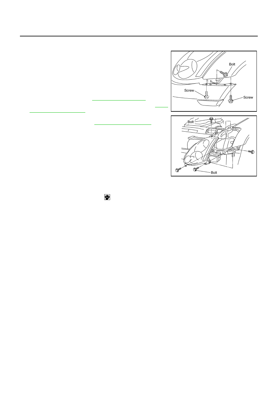
4.
Remove mounting clip on top of front bumper and screws on
side of front bumper. Refer to
.
5.
Pull side of front bumper toward the vehicle front and disengage
it from clips on the body.
6.
Remove headlamp mounting bolts.
7.
Pull headlamp toward the vehicle front, disconnect connector,
and remove headlamp.
CAUTION:
When removing headlamps, put a shop cloth or something
similar between headlamps and bumper to protect bumper.
INSTALLATION
Installation is the reverse order of removal.
PKIA2392E
PKIA2393E
Headlamp mounting bolt
: 5.9 N·m (0.60 kg-m, 52 in-lb)