Infiniti G35 (V35). Manual - part 479
TIMING CHAIN
EM-71
C
D
E
F
G
H
I
J
K
L
M
A
EM
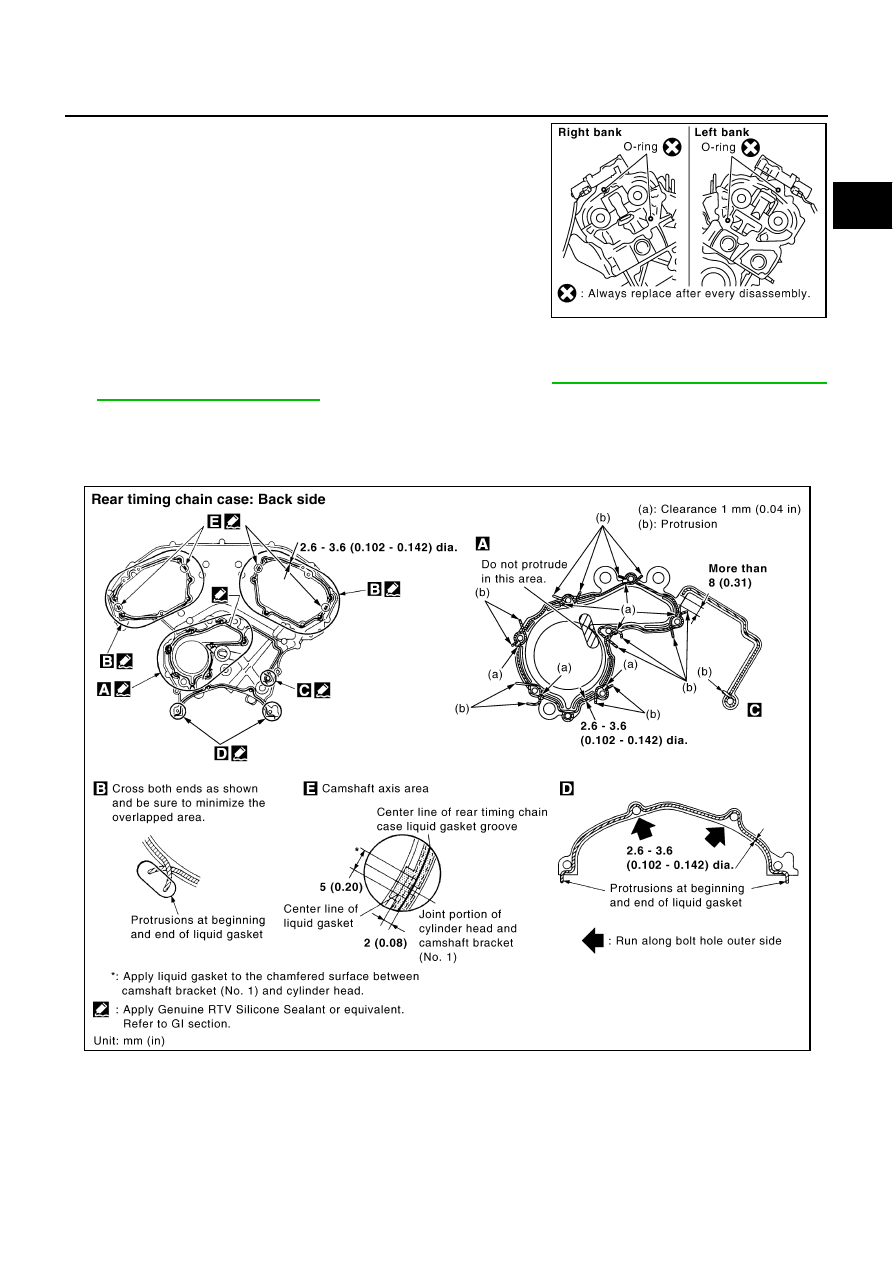
b.
Install new O-rings to cylinder head.
c.
Apply liquid gasket with tube presser [SST: WS39930000 (
—
)] to rear timing chain case back side as
shown in the figure.
Use Genuine RTV Silicone Sealant or equivalent. Refer to
.
CAUTION:
●
For “A” in the figure, completely wipe out liquid gasket extended on a portion touching at
engine coolant.
●
Apply liquid gasket on installation position of water pump and cylinder head very completely.
d.
Align rear timing chain case and water pump assembly with dowel pins (right and left) on cylinder block
and install rear timing chain case.
●
Make sure O-rings stay in place during installation to cylinder block and cylinder head.
SBIA0496E
PBIC2680E