Index Infiniti Infiniti G35 (V35) Coupe - service repair manual 2007 year
Search
Content .. 272 273 274 275 ..
Infiniti G35 (V35). Manual - part 274
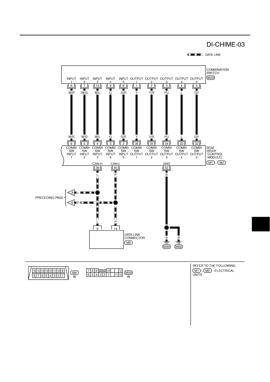
WARNING CHIME
DI-43
C
D
E
F
G
H
I
J
L
M
A
B
DI
TKWM2169E