Infiniti G35 (V35). Manual - part 252


  Index      Infiniti     Infiniti G35 (V35) Coupe - service repair manual 2007 year


Search            


Content   ..  250  251  252  253   ..


Infiniti G35 (V35). Manual - part 252


CLUTCH PEDAL

CL-5

D

E

F

G

H

I

J

K

L

M

A

B

CL

CLUTCH PEDAL

PFP:46540

On-Vehicle Inspection and Adjustment

NCS000A0

1.

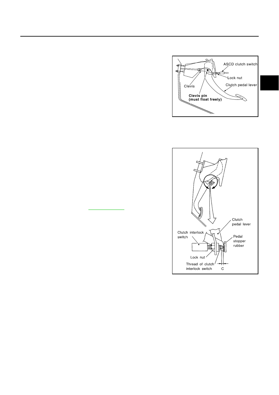
Check to see if clevis pin floats freely in the bore of clutch pedal.
It should not be bound by clevis or clutch pedal. 

a.

If clevis pin is not free, check that ASCD clutch switch is not
applying pressure to clutch pedal causing clevis pin to bind. To
adjust, loosen lock nut and turn ASCD clutch switch. 

b.

Tighten lock nut.

c.

Verify that clevis pin floats in the bore of clutch pedal. It should
not be bound by clutch pedal.

d.

If clevis pin is still not free, remove clevis pin and check for
deformation or damage. Replace clevis pin if necessary. Leave
pin removed for step 2.

2.

Check clutch pedal stroke for free range of movement.

a.

With clevis pin removed, manually move clutch pedal up and down to determine if it moves freely.

b.

If any sticking is noted, replace the related parts (clutch pedal bracket, assist spring, bushing etc.) Re-
assemble clutch pedal and re-verify that clevis pin floats freely in the bore of clutch pedal. 

3.

Adjust clearance “C” while depressing clutch pedal fully.(With
clutch interlock switch)

4.

Check clutch hydraulic and system components (clutch master
cylinder, clutch operating cylinder, clutch withdrawal lever, clutch
release bearing, etc.) for sticking or binding.

a.

If any sticking or binding noted, repair or replace related parts as
necessary.

b.

If hydraulic system repair was necessary, bleed the clutch
hydraulic system. Refer to 

CL-7, "Bleeding"

 . 

NOTE:
Do not use a vacuum assist or any other type of power bleeder
on this system. Use of a vacuum assist or power bleeder will not
purge all the air from the system.

Clearance C

: 0.1 - 1.0 mm (0.004 - 0.039 in)

PCIB0680E

SCL800

CL-6

CLUTCH PEDAL

Removal and Installation

NCS000A1

COMPONENTS

REMOVAL

1.

Remove kicking plate. Refer to 

EI-31, "Removal and Installation"

 .

2.

Remove foot-rest. Refer to 

EI-34, "Removal and Installation"

 .

3.

Remove dash side finisher. Refer to 

EI-31, "Removal and Installation"

 .

4.

Remove instrument lower driver panel. Refer to 

IP-11, "Removal and Installation"

 .

5.

Remove VDC/TCS/ABS control unit. Refer to 

BRC-59, "Removal and Installation"

 .

6.

Remove clutch interlock switch and ASCD clutch switch connector and harness.

7.

Remove snap pin and clevis pin.

8.

Remove pedal bracket mounting bolt and nuts and then remove clutch pedal assembly.

INSPECTION AFTER REMOVAL

Check clutch pedal for bend, damage, or a cracked weld. If bend, damage, or a cracked weld is found,
replace clutch pedal assembly.

INSTALLATION

To install, reverse the removal procedure, following the cautions below:

Install clutch pedal assembly and adjust the pedal height. Tighten ASCD clutch switch lock nut to the
specified torque.

After installing clutch interlock switch, adjust the switch position.

NOTE:
Tighten ASCD clutch switch lock nut to the specified torque after installing clutch pedal assembly in vehicle
and adjusting the pedal free play.

1.

Clutch interlock switch

2.

Bracket

3.

Clevis pin

4.

Pedal stopper rubber

5.

Clutch pedal

6.

Stopper rubber

7.

Pedal pad

8.

ASCD clutch switch

9.

Bushing

10. Snap pin

Refer to 

GI-10, "Components"

 , and the followings for the symbols in the figure.

: Apply lithium-based grease including molybdenum disulphide.

SCIA7469E

CLUTCH FLUID

CL-7

D

E

F

G

H

I

J

K

L

M

A

B

CL

CLUTCH FLUID

PFP:00017

Bleeding

NCS000A2

CAUTION:

Monitor fluid level in reservoir tank to make sure it does not empty.

Do not spill clutch fluid onto painted surfaces. If it spills, wipe up immediately and wash the
affected area with water.

NOTE:
Do not use a vacuum assist or any other type of power bleeder on this system. Use of vacuum assist or power
bleeder will not purge all the air from the system.

1.

Fill master cylinder reservoir tank with new clutch fluid.

2.

Connect a transparent vinyl hose to air bleeder.

3.

Depress clutch pedal quickly and fully a few times and hold it.

4.

With clutch pedal depressed, open air bleeder.

5.

Close air bleeder.

6.

Release clutch pedal and wait for 5 seconds.

7.

Repeat steps 3 to 6 until no bubbles can be observed in brake
fluid.

8.

Tighten air bleeder to the specified torque. Refer to 

CL-11,

"Components"

 .

PCIB1305J

CL-8

CLUTCH MASTER CYLINDER

CLUTCH MASTER CYLINDER

PFP:30610

Components

NCS001AD

Removal and Installation

NCS000A3

REMOVAL

1.

Remove kicking plate. Refer to 

EI-31, "Removal and Installation"

 .

2.

Remove foot-rest. Refer to 

EI-34, "Removal and Installation"

 .

3.

Remove dash side finisher. Refer to 

EI-31, "Removal and Installation"

 .

4.

Remove instrument lower driver panel. Refer to 

IP-11, "Removal and Installation"

 .

5.

Remove VDC/TCS/ABS control unit. Refer to 

BRC-59, "Removal and Installation"

 .

6.

Remove snap pin and clevis pin from clevis, and separate it from clutch pedal.

7.

Remove hoodledge cover.

8.

Drain clutch fluid in reservoir tank and remove reservoir hose.

CAUTION:

Do not spill clutch fluid onto painted surfaces. If it spills, wipe up immediately and wash the
affected area with water.

1.

Nipple

2.

Clamp

3.

Reservoir hose

4.

Cylinder body

5.

Packing

6.

Seat

7.

Clevis

8.

Clevis pin

9.

Snap pin

10. Stopper ring

11.

Stopper

12. Push rod

13. Piston assembly

14. Return spring

15. Reservoir seal

16. Spring pin

Refer to 

GI-10, "Components"

 , and the followings for the symbols in the figure.

1: Apply lithium-based grease including molybdenum disulphide.

2: Apply rubber lubricant.

3: Apply silicone grease.

SCIA7470E


Content   ..  250  251  252  253   ..