Infiniti G20 (P11). Manual - part 32
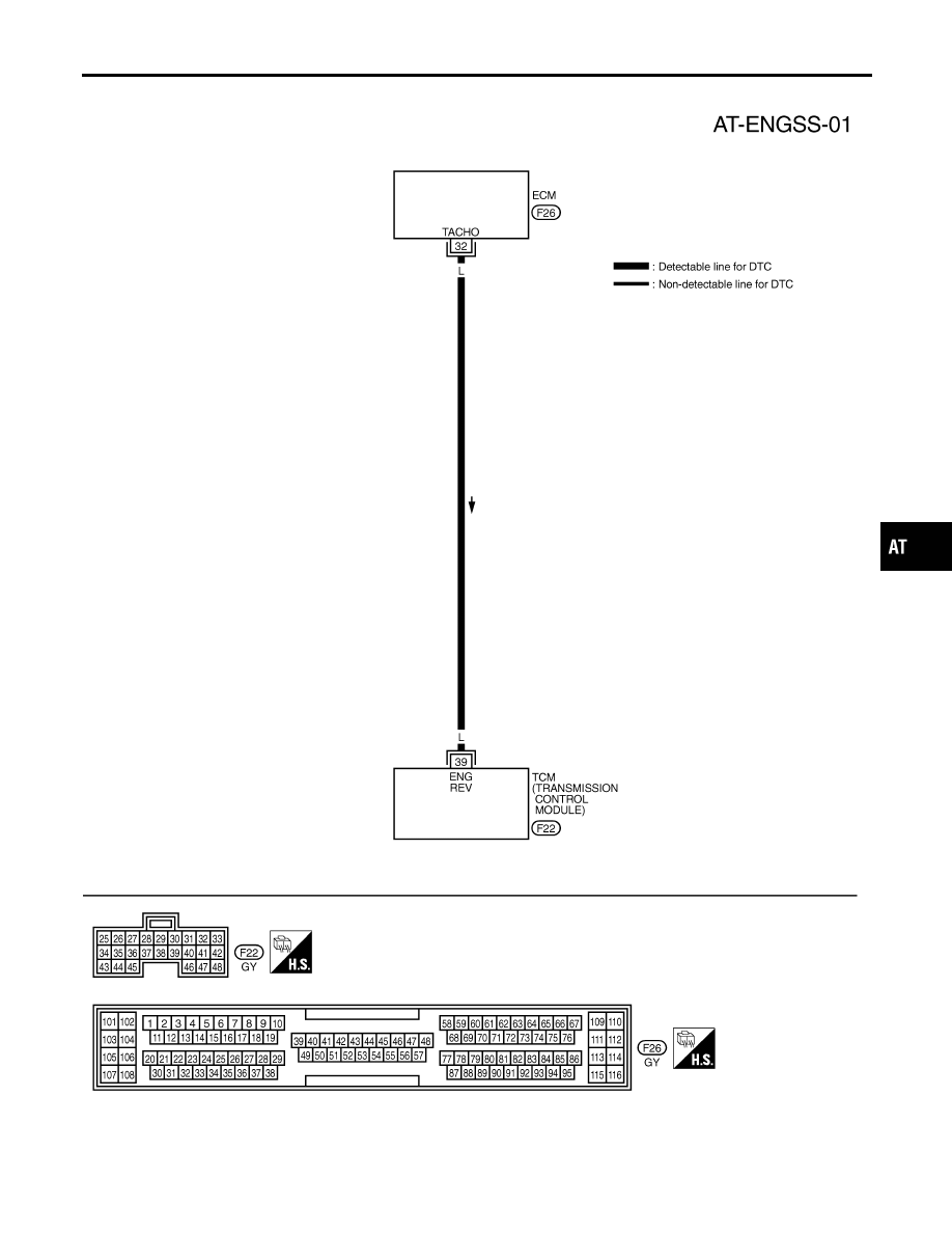
Wiring Diagram — AT — ENGSS
NCAT0202
TAT226
GI
MA
EM
LC
EC
FE
CL
MT
AX
SU
BR
ST
RS
BT
HA
SC
EL
IDX
DTC P0725 ENGINE SPEED SIGNAL
Wiring Diagram — AT — ENGSS
AT-125
|
|
|
Wiring Diagram — AT — ENGSS NCAT0202 TAT226 GI MA EM LC EC FE CL MT AX SU BR ST RS BT HA SC EL IDX DTC P0725 ENGINE SPEED SIGNAL Wiring Diagram — AT — ENGSS AT-125 |