Hummer H3. Manual - part 90


  Index      Hummer     Hummer H3 - service repair manual 2006-2009 year


Search            


Content   ..  88  89  90  91   ..


Hummer H3. Manual - part 90


1. Clamp the camshaft actuator in a vice. Use care not to damage the contact area of the 

sprocket. 

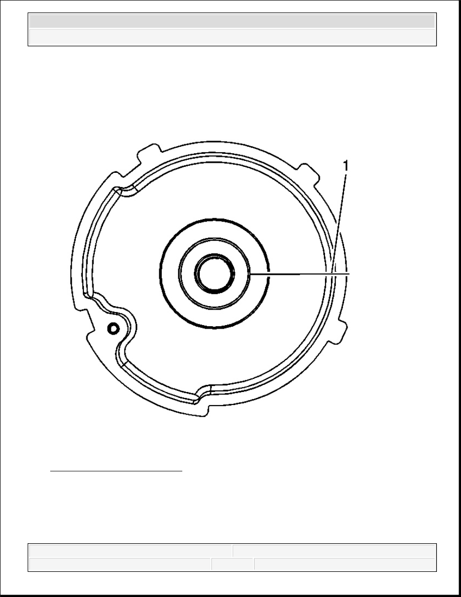
Fig. 29: Scribe or draw a line 
Courtesy of GENERAL MOTORS CORP. 

2. Scribe or draw a line (1) on the camshaft position actuator outer ring face, in the full 

advanced position. With the engine at TDC on #1 cylinder, the wording should be level. 


2006 Hummer H3 

2006 ENGINE Engine Mechanical - 3.5L (L52) - H3


Fig. 30: Wording Should Be Level 
Courtesy of GENERAL MOTORS CORP. 

3. Apply compressed air pressure to the oil port (1) on the back side of the actuator to unlock 

the locking pin.  

4. Turn the actuator, by hand, to the full counterclockwise position.  

5. Scribe or draw a line (2) on the camshaft position actuator at that position. 


2006 Hummer H3 

2006 ENGINE Engine Mechanical - 3.5L (L52) - H3


Fig. 31: Scribe or draw a 2nd line 
Courtesy of GENERAL MOTORS CORP. 

6. Measure the distance between the two lines. The measurement (3) should be 14-15 mm 

(0.55-0.59 in). 

IMPORTANT: It is normal for oil to leak out of the camshaft actuator when 

compressed air is applied. It is also normal for oil bubbles to 
form on the camshaft sprocket itself.


2006 Hummer H3 

2006 ENGINE Engine Mechanical - 3.5L (L52) - H3


Fig. 32: Measure The Distance Between The Two Lines 
Courtesy of GENERAL MOTORS CORP. 

The camshaft position actuator must be replaced if it does not unlock when air pressure is 
applied, does not lock when air pressure is removed, or does not move within the 14-15 mm 
(0.55-0.59 in). 

REPAIR INSTRUCTIONS 

DRIVE BELT REPLACEMENT (WITHOUT A/C) 

Removal Procedure 


2006 Hummer H3 

2006 ENGINE Engine Mechanical - 3.5L (L52) - H3


Content   ..  88  89  90  91   ..