Hummer H1 (1992-1998). Manual - part 26


  Index      Hummer     Hummer H1 - service repair manual 1992-1998 year


Search            


Content   ..  24  25  26  27   ..


Hummer H1 (1992-1998). Manual - part 26


2-32. FUEL INJECTION PUMP REPAIR (Cont’d)

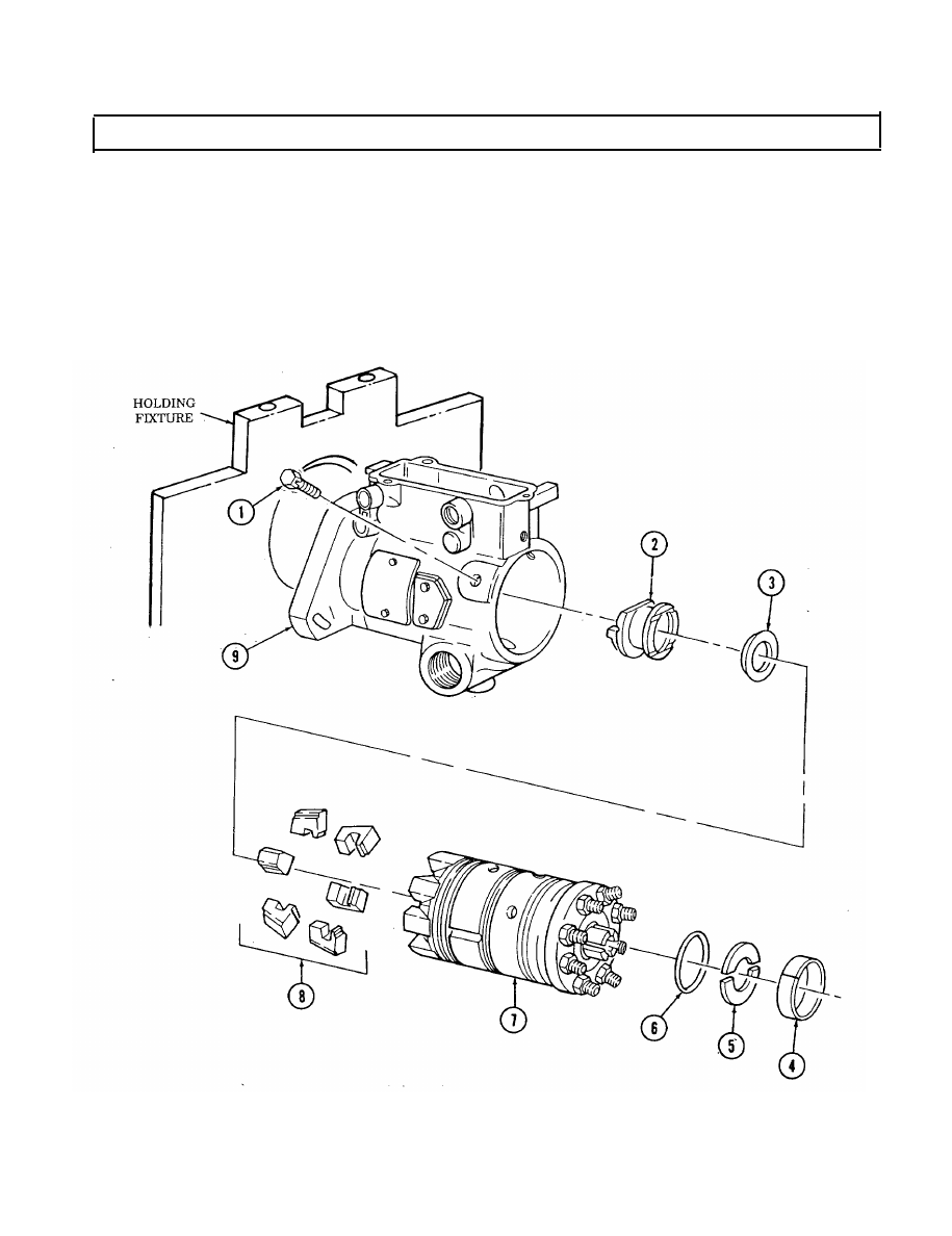
40. Rotate housing (9) and holding fixture right side up.
41. Remove head locking capscrew (1).
42. Remove hydraulic head assembly (7) from housing (9).
43. Remove six weights (8), washer (3), and governor thrust sleeve (2) from hydraulic head (7).

44. Remove liner locating ring (4) and two rotor retainers (5) from hydraulic head (7).

45.

Remove transfer pump end cap seal (6) from hydraulic head (7). Discard seal (6).

2-92

2-32. FUEL INJECTION PUMP REPAIR (Cont’d)

46. Remove snapring (10) and weight retainer (11) from rotor (13).

NOTE

Note direction of arrow on cam ring indicating rotation of pump
for assembly.

47. Remove cam ring (12) from hydraulic head (7).

2-93

2-32. FUEL INJECTION PUMP REPAIR (Cont’d)

48. Remove two cam roller shoes (2) and two cam rollers (1) from rotor (4).

49. Remove leaf spring adjusting screw (7) and leaf spring (6) from rotor (4).

50. Remove two plungers (3) from rotor (4).
51. Install governor weight support in vise.

CAUTION

Do not handle precision ground surface of rotor to avoid
contamination.

Handle all parts carefully with clean hands wet with calibrating
fluid to avoid contamination.

52. Remove rotor (4) from hydraulic head (5) and place rotor (4) in governor weight support. Using

5/32-in. hex head driver, remove delivery valve stop plug (12).

53. Remove head seal (8) from hydraulic head (5). Discard head seal (2).

NOTE

If delivery valve cannot be removed from rotor, delivery valve

extractor must be used.

54. Remove valve stop (11), spring (10), and delivery valve (9) from rotor (4). Discard valve stop (11) and

tag spring (10) for assembly.

2-94

2-32. FUEL INJECTION PUMP REPAIR (Cont’d)

55. Remove drive shaft snapring (18) and drive shaft (15) from housing (17).
56. Remove two black seals (22) and red seal (16) from drive shaft (15). Discard seals (22) and (16).
57. Remove thrust button (13) and spring (14) from drive shaft (15) and tag spring (14) for assembly.
58. Remove two screws (20), timing cover (21), and gasket (19) horn housing (17). Discard gasket (19).
59. Remove housing (17) from holding fixture.

2-95


Content   ..  24  25  26  27   ..