Great Wall Florid. Manual - part 49


  Index      Great Wall     Great Wall Florid - service repair manual 2008 year


Search            copyright infringement  


Content   ..  47  48  49  50   ..


Great Wall Florid. Manual - part 49


GWFLORID Maintenance Manual

194

Display character

Malfunction

Solutions

ERR3

Disc is placed upside down

Eject the disc and reload

ERR4

Incompatible disc file or format

Check the disc format

ERR1
ERR1

Disc structure error

Eject the disc and replay

Trouble code

Electrical connection diagram

Symptoms

Causes

Solutions

The sound quality is poor or 

distorted

Speaker's connection wire touches the 

vehicle body

Check the speaker's connection wire

"MUTE" wire touches the metal parts 

of the vehicle body

Ensure the telephone silence control wire is 

insulated from the vehicle body

A connection error between the 

ignition coil ACC and positive power 

line "BATT"

Please refer to the "Eelectrical connection 

diagram" to correct the connection
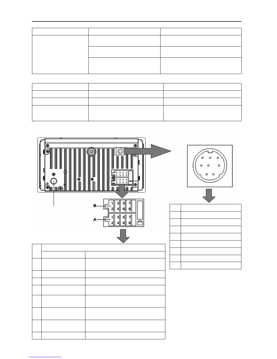
Radio antenna

1

2

3

4

5

6

7

8

Pin

Definition

1

Karaoke control wire

2

Microphone audio output

3

Power supply (+)

4

Microphone audio ground cable

5

Auxiliary left audio output

6

Auxiliary right audio output

7

Auxiliary audio ground cable

8

Power supply ground cable

Pin

Function

A

B

1

Linear control ground 
cable

Rear horn RH (+) (Violet)

2 Mute (Pink)

Rear horn RH (-) (Violet/Black striped)

3 Linear control

Front horn RH (+) (Grey)

4 Connected ignition 

swith (Red)

Front horn RH (-) (Grey/Black striped)

5

Automatic antenna 
(Blue/White)

Front horn LH (+) (White)

6

Lighting wire 
(Brown)

Front horn LH (-) (White/Black striped)

7

to engine battery 
positive (+) (Yellow)

Rear horn LH (+) (Green)

8 Ground cable (Black) Rear horn LH (-) (Green/Black striped)

ISO pin definition

195

Electrical Accessories

Head unit ISO interface definition

Pin

Pin definition

1

Power supply ground cable

2

Headlight diagnostic

3

Ignition diagnostic

4

Mute diagnostic

5

Power supply +

6

Radio antenna power supply control

7

Key-drive

8

Key-drive ground cable

9

15 A fuse

10

15 A fuse 

Pin

Pin definition

Pin

Pin definition

11

Rear left audio output -

21

Disc changer communication wire (reserve)

12

Front left audio output -

22

Power supply ground cable (reserve)

13

Front right audio output -

23

Communication wire (reserve)

14

Rear right audio output -

24

Disc changer right-channel output (reserve)

15

Rear left audio output +

25

Power supply + (reserve)

16

Front left audio output +

26

Audio ground cable (reserve)

17

Front right audio output +

27

Key-drive ground cable

18

Rear right audio output +

28

Amplifier control

19

Disc changer left-channel output (reserve)

29

Key-drive B

20

Ignition diagnostic (reserve)

30

Key-drive A

DVD Player

Head unit outside view

GWFLORID Maintenance Manual

196

Head unit 36 PIN socket definition

Pin

Pin definition

Pin

Pin definition

Pin

Pin definition

1 Auxiliary audio ground cable

13 Navigator communication line 

(head unit receive)

25 Rear right audio output (reserve)

2 Auxiliary left audio input

14 Navigator communication line 

(reserve)

26 Mid-audio output (reserve)

3 Auxiliary right audio input

15 Digital ground cable

27 Super bass audio output (reserve)

4 Digital ground cable

16 Navigator composite video signal 28 Audio ground cable (reserve)

5 Auxiliary video input

17 Navigator red video signal

29 Background left audio output 

(reserve)

6 SV-6269:Karaoke control wire 

SV-6268: NC

18 Digital ground cable

30 Background right audio output 

(reserve)

7 Power supply +

19 Navigator green video signal

31 Background video output 1 

(reserve)

8 Ignition diagnostic

20 Navigator blue video signal

32 Auxiliary audio input 2 (reserve)

9 Navigator audio input

21 Front left audio output (reserve) 33 Digital ground cable (reserve)

10 SV-6269:Microphone audio input 

SV-6268: NC

22 Front right audio output (reserve) 34 Audio ground cable (reserve)

11 Navigator audio ground cable 23 Audio ground cable (reserve)

35 Auxiliary left audio output 2 

(reserve)

12 Navigator communication line 

(head unit send)

24 Rear left audio output (reserve)

36 Auxiliary right audio input 2 

(reserve)

Karaoke box MINI8PIN socket

Pin

Pin definition

1

Karaoke control wire

2

Microphone audio output

3

Power supply +

4

Microphone audio ground cable

5

Auxiliary left audio output

6

Auxiliary right audio output

7

Auxiliary audio ground cable

8

Power supply ground cable

8

7

6

3

4

5

2

1

Pin

Pin definition

Pin

Pin definition

31

Brake diagnostic

35

Rearview mirror power supply

32

Reverse diagnostic

36

Rearview mirror power supply ground 

cable

33

Disc changer video input (reserve)

37

Rearview mirror video input

34

Video ground cable

38

Video ground cable

197

Electrical Accessories

Common faults and solutions

If the following faults occur while using this machine, please refer to the troubleshooting guide.

General problems

Symptoms

Causes

Solutions

Cannot start

Burnt fuse

Replace with a new fuse of the same 

specification

Vehicle supply battery fuse is burnt

Replace the vehicle supply battery fuse

Illegal operation and other factors

Press the reset button to reset the system

Remote controller doesn't 

work

Remote controller battery is low

Replace the remote controller battery

Remote controller battery is reversely 

installed

Proper battery installation

No sound or sound is too low

The volume of the head unit or the 

connected component is too low

Raise the volume of the head unit or the 

connected component

Speaker possibly damaged

Check the speaker

The sound balance settings lean to one 

side

Adjust the sound balance

Speaker's connection wire touches the 

vehicle body

Use insulated conductor to connect the 

speaker and use insulating cement to cover 

the exposed connections

Disc is not genuine

Use a genuine disc

Speaker is incorrectly connected

Please refer to the "Equipment connection 

drawing" to correct the connection

The sound quality is poor or 

distorted

Speaker's connection wire touches the 

vehicle body

Check the speaker's connection wire

"MUTE" wire touches the metal parts of 

the vehicle body

Ensure the telephone silence control wire 

is insulated from the vehicle body

A connection error between ignition coil 

ACC and positive power wire "BATT"

Please refer to the "equipment connection 

drawing" to correct the connection

Common display characters and fault meaning

Display character

Malfunction

Solutions

No Disc 

Disc is dirty

Clean or replace the disc

The read side of the disc is inserted 

upside-down

Insert the disc into the player with the 

label side up

No disc in the player

Insert the disc

Bad disc 

Disc is dirty

Clean or replace the disc

The read side of the disc is reversely 

inserted

Insert the disc into the player with the 

label side up

Unknown disc 

Player cannot read disc

Please use discs supported by this player

Region error 

The region code of this disc does not 

match the region code for this player

Use discs that have a region code identical 

to this player's


Content   ..  47  48  49  50   ..