Great Wall Florid. Manual - part 37


  Index      Great Wall     Great Wall Florid - service repair manual 2008 year


Search            copyright infringement  


Content   ..  35  36  37  38   ..


Great Wall Florid. Manual - part 37


GWFLORID Maintenance Manual

146

Main relay

10A backup 

15A backup 

25A backup 

Compressor relay

Reserve

Reserve 

Fuel pump 

Starter relay 

Main 

relay 

High 

beam 

Low 

beam  Engine ECU 

Fan relay High

Starter relay

High beam relay Low beam relay

Reserve

Horn  

Reserve  Reserve  Fan relay Low 

Fan relay Low

Fan relay High 

Horn relay

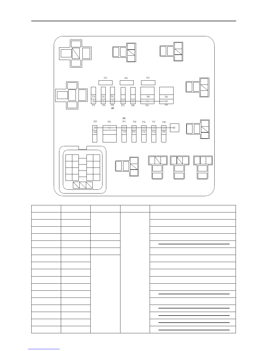
Engine compartment No.2 fuse box

Fuse number and bearer circuit

Fuse number Current rating

Fuse type

Power

Bearer circuit

F29

30 A

AutoFuse

30 Battery (+)

Starter relay

F30

25 A

Main relay

F31

15 A

Fuel pump relay

F32

30 A

Slow burn fuse 

Low speed fan relay

F33

Reserve

AutoFuse 

F34

30 A

Slow burn fuse 

High speed fan relay

F35

15 A

AutoFuse 

High & low pitched horn

F36

15 A

High beam light relay

F37

15 A

Low beam light relay

F38

10 A

Engine ECU, diagnostic port

F39

25 A

ABS ECU

F40

Reserve

F41

15 A

AM2

F42

Reserve

F43

Backup 10 A

F44

Backup 15 A

F45

Backup 25 A

147

Vehicle Body Electronic System

Eilte

Cab No.1 fuse box back side pin diagram

Connected dashboard's 

wire harness A

Connected dashboard's 

wire harness B

Connected dashboard's 

wire harness C

Connected dashboard's 

wire harness D

Connected dashboard's 

wire harness E

Connected dashboard's 

wire harness H

A

B

C

D

E

F

H

(Elite)

GWFLORID Maintenance Manual

148

Plug-in connector pin's function

Pin number

Function

Pin number

Function

A01

Rear fog lamp

A11

Empty

A02

Internal lighting

A12

Empty

A03

Empty

A13

Empty

A04

Combination switch 

(front fog lamp)

A14

Empty

A05

Combination meter 

A15

Empty

A06

Front fog lamp

A16

Empty

A07

Empty

A17

Empty

A08

Empty

A18

Empty

A09

Central lock controller

A19

Empty

A10

Combination switch 

(rear fog lamp)

A20

Empty

B01

Power IG (12v)

B10

Empty

B02

Ground

B11

Empty

B03

Power rearview mir-

ror switch, CD

B12

Window regulator motor

B04

Ignition switch (ACC)

B13

Front & rear cigarette 

lighter, backup 

power supply

B05

Empty

B14

Empty

B06

Compressor control

B15

Reverse lamp, air 

conditioner controller

B07

Empty

B16

Empty

B08

Front wiper, front and 

rear washer motor

B17

Empty

B09

Ground

B18

Empty

C01

Air conditioner con-

troller (blower) 

C08

Rear glass and rearview 

mirror defroster 

C02

Air conditioner 

controller (defroster) 

C09

Empty

C03

Airbag ECU 

C10

Empty

C04

Combination switch 

(rear wiper) 

C11

Empty

C05

ABS ECU

C12

Empty

C06

Rear wiper power reset

C13

Combination meter 

C07

Rear wiper motor

C14

Rear wiper reset

149

Vehicle Body Electronic System

Plug-in connector pin's function (Continued)

Pin number

Function

Pin number

Function

D01

Combination switch 

(right turn)

D09

Ignition switch (AM1) 

D02

Combination switch 

(left turn)

D10

Combination switch 

(parking lamp)

D03

Right turn signal lamp

D11

Parking lamp, meter 

brightness

D04

Ground

D12

Sunroof (Elite)

D05

Hazard warning switch

D13

Empty

D06

Empty

D14

Empty

D07

Left turn signal lamp

D15

Empty

D08

Empty

D16

Empty

E01

Compressor

E05

Empty

E02

Stereo

E06

Empty

E03

Empty

E07

Empty

E04

Brake switch

E08

Empty

H01

Blower

F01

Blower high speed


Content   ..  35  36  37  38   ..