Great Wall Florid. Manual - part 9


  Index      Great Wall     Great Wall Florid - service repair manual 2008 year


Search            copyright infringement  


Content   ..  7  8  9  10   ..


Great Wall Florid. Manual - part 9


GWFLORID Maintenance Manual

34

Exhaust System Removal

Caution: Wait at least 30 minutes between the engine 

being turned off and the actual removal of any component 

of the exhaust system, as to avoid personnel injury due to 

hot components.

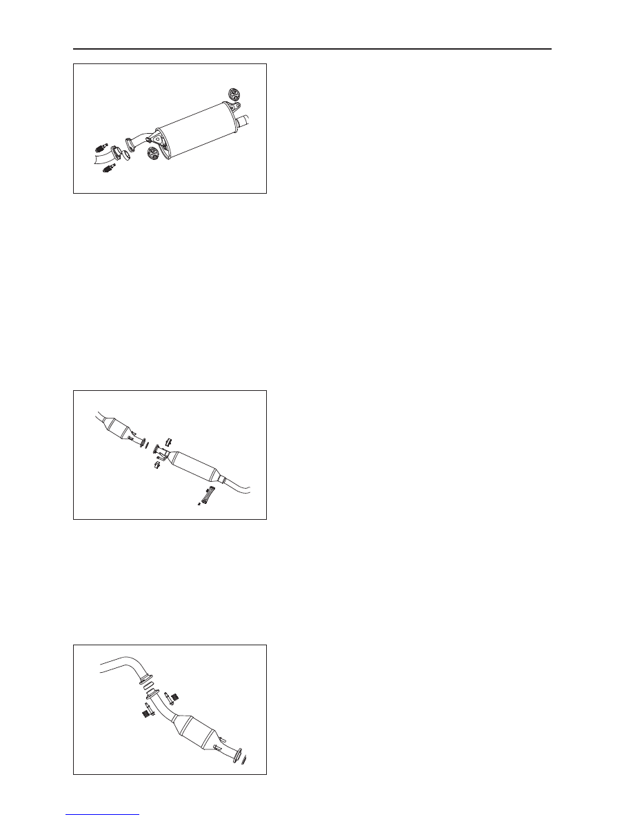
1.  Main muffler assembly removal

(a)  First use a No. 13 wrench (open), sleeve, or ratchet 

spanner to remove the connecting spring bolt between 

the front flange of the main muffler assembly and the 

rear flange of the sub-muffler. Then take out the gasket 

between the flanges.

(b)  Remove the two rubber hangers on the main muffler.

(c)  Take down the main muffler assembly.

Caution: The sealing ring between the front flange of 

the main muffler assembly and the rear flange of the 

sub-muffler is used only for sealing. If reused, it may 

cause large deformations and result in a poor sealing 

effect. Accordingly, it is suggested not to use a sealing 

ring repeatedly. If necessary, only one repetition should 

be allowed.

Warning: While performing this kind of maintenance 

work, a person should be present to support the main 

muffler to avoid injury in case the muffler falls.

2.  Sub-muffler assembly removal

(a)  Use a No. 14 wrench (open), sleeve, or ratchet wrench 

to remove the connecting bolt between the front flange 

of the sub-muffler assembly and the rear flange of the 

catalyst assembly.

(b)  Remove the support of the sub-muffler plate bracket.

(c)  Remove the two two-hole rubber hangers between the 

sub-muffler and the frame.

(d)  Take down the sub-muffler assembly.

Caution: The sealing ring between the front flange of 

the sub-muffler and the rear flange of the catalyst as-

sembly is used only for sealing. If reused, it may cause 

large deformations and result in a poor sealing effect. 

Accordingly, it is suggested not to use a sealing ring 

repeatedly. If necessary, only one repetition should be 

allowed.

Warning: While performing this kind of maintenance 

work, a person should be present to support the sub-

muffler to avoid injury in case the muffler falls.

3.  Rear catalytic assembly removal

(a)  Remove the connecting spring bolt between the front 

flange of the sub-muffler assembly and the rear flange 

of the rear catalytic assembly. Then take out the sealing 

ring between the flanges.

(b)  Take off the rear catalytic assembly.

35

Fuel Supply and Exhaust System

4.  Front exhaust pipe removal

(a)  Use a No. 14 wrench (open), sleeve, or ratchet wrench 

to remove the connecting nut between the front flange 

of the front exhaust pipe assembly and the flange of the 

exhaust manifold. Then take out the gasket between the 

flanges.

(b)  Carefully remove the front exhaust pipe from the 

subframe.

Caution: The gasket between the front flange of the 

front  exhaust  pipe  and  the  flange  of  the  exhaust 

manifold are used only for sealing. If reused, they may 

cause large deformations and result in a poor sealing 

effect. Accordingly,  it  is  suggested  not  to  use  the 

sealing ring repeatedly.

Exhaust System Installation

1.  The clearance between the exhaust pipe assembly and 

both sides of the individual components should be no 

less than 15 mm.

2.  Before installing rubber hangers, coat a proper amount 

of silicon oil in holes. After installation, even force 

should be applied.

3.  After installing the center exhaust pipe with the three-

way catalytic converter assembly, ensure the plug of 

the oxygen sensor is well connected.

GWFLORID Maintenance Manual

36

Clutch Operational System

Areas of Importance ...........................................................37
Troubleshooting ..................................................................37
Clutch Operational System .................................................38
  Components .....................................................................38
  Clutch Master Cylinder Removal ......................................38
  Clutch Master Cylinder Installation ...................................40
  Clutch Pedal Removal ......................................................40
  Clutch Pedal Installation ...................................................40
  Clutch Pedal Examination and Adjustment.......................41

37

Clutch Operational System

Areas of Importance

1.  Clutch Rigid Pipe Installation

Before installing, check to make sure that the rigid pipe flare contact area is in good condition, the pipeline is 

clean, and that there is no foreign materials.

2.  Clutch Hose Installation

Check the surface of the clutch hose to make sure that there is no scuffing and that the pipeline is clean.

3.  Coat grease on the U-joint of the pedal and the master cylinder.

4.  Strictly adhere to the set torque guidelines when tightening the pipe fittings.


Rigid pipe and the master cylinder: M10 16±2 N·m


Clutch rigid pipe and hose: M10 16±2 N·m

5.  While the clutch system is undergoing the exhausting process, make sure that all the air bubbles in 

the pipeline are cleared out. Then check the brake fluid level in the reservoir, it should be between 

MIN and MAX.

Troubleshooting

The numbers in the table represent the order of the possible malfunction causes, so be sure to check each part in 

turn. If necessary, replace the part.

Symptoms

Possible Causes

Clutch vibration

1. Engine mounting bracket (loose)
2. Clutch plate (axial runout is too much)
3. Clutch plate (oil build-up)
4. Clutch plate (polished)
5. Clutch plate (hardened)
6. Diaphragm spring (damaged)

Clutch pedal is spongy

1. Clutch pipeline (air entering)
2. Clutch master cylinder cup (damaged)
3. Clutch slave cylinder cup (damaged)

Clutch makes abnormal noise

1. Clutch release bearing (wear and tear, dirty or damaged)
2. Driven plate torsion damper (damaged)

Clutch slips

1. Clutch pedal (free play is out of alignment)
2. Clutch plate (oil build-up)
3. Clutch plate (polished)
4. Diaphragm spring (damaged)
5. Pressure plate (deformed)
6. Flywheel (deformed)

Clutch cannot be disengaged

1. Clutch pedal (free play out of alignment)
2. Clutch pipeline (air entering)
3. Clutch master cylinder cup (damaged)
4. Clutch slave cylinder cup (damaged)
5. Clutch plate (axial runout is too much)
6. Clutch plate (wear out from friction)
7. Clutch plate (dirty or burnt)
8. Clutch plate (oil build-up)
9. Clutch plate (lack of grease on the spline)


Content   ..  7  8  9  10   ..