Great Wall Florid. Manual - part 8
30
GWFLORID Maintenance Manual
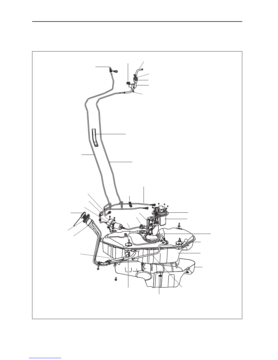
Fuel Supply System
Components
Fuel filler hose III
Canister solenoid valve
Canister solenoid valve installation sheath
Canister solenoid valve mounting bracket assembly
Fuel hose sheath
Desorption fuel hose
Fuel filler hose
Desorption hose I
Fuel filler hose II
Three-hole
clamp I
Charcoal canister
Fuel tank assembly
Fuel tank heat shield
assembly
Charcoal canister air pipe
Air return hose
Fuel filler pipe assembly
Electronic fuel pump
Single-hole clamp
Electronic fuel pump install panel
Strengthening cushion
Fuel filler pipe
connecting hose
Absorption hose
Fuel filler pipe sleeve
Single-hole clamp
Fuel filter
Rear install buckle of fuel tank's heat shield
Fuel filler cap
Fuel filler hose I
Desorption hose III
Desorption hose II
Fuel filter mounting bracket
assembly