Geely Emgrand X7. Manual part - 652


  Главная      Geely     Geely Emgrand X7 - Manual


поиск по сайту          


содержание   ..   650  651  652  653  ..


Geely Emgrand X7. Manual part - 652


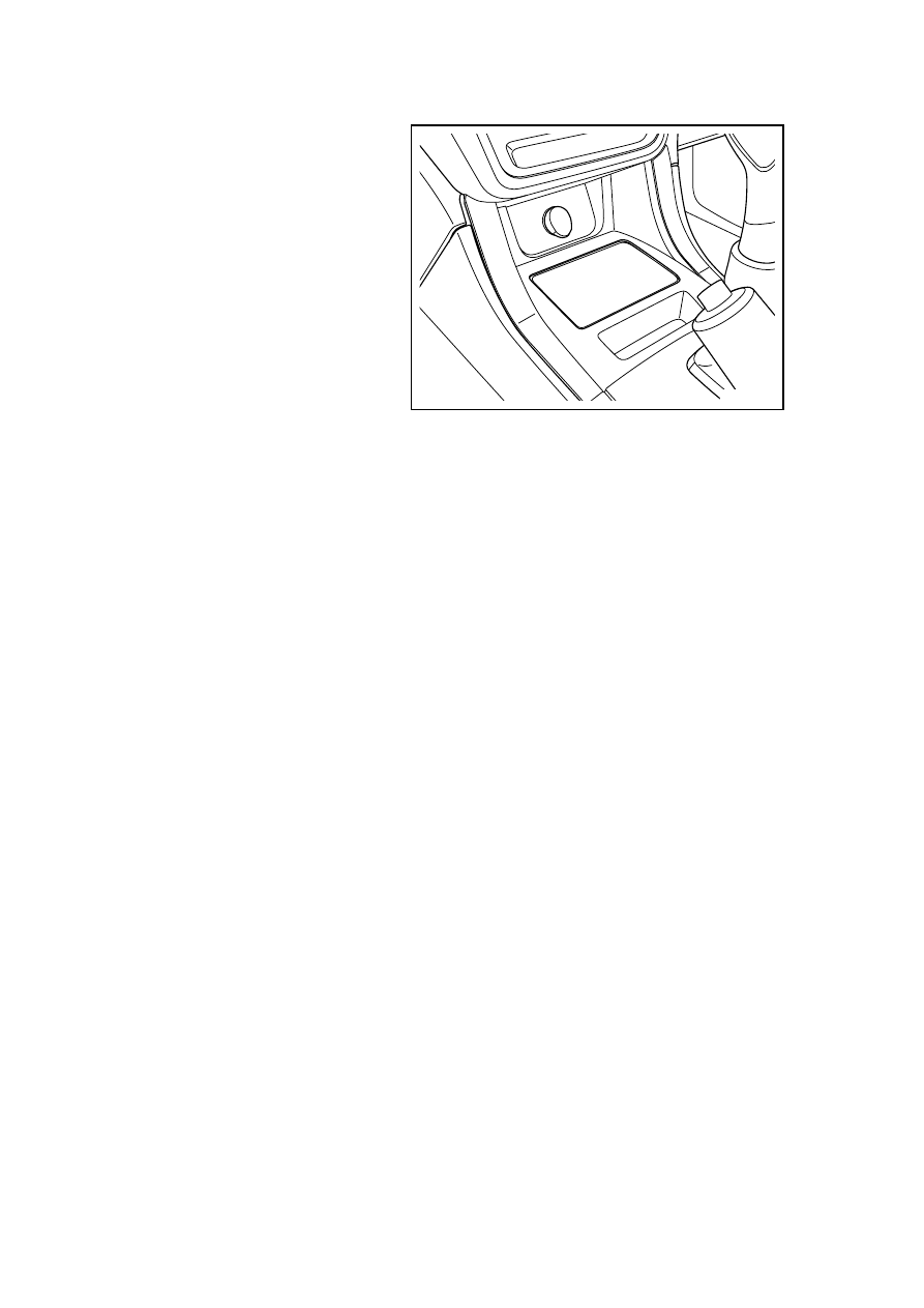
2.  Install standby power supply. 

3.  Install auxiliary instrument panel 

ashtray panel. 

4.  Connect the battery negative 

cable. 

NL11-0118b

2607

11.16 Data communication system 

11.16.1 Specifications 

11.16.1.1 Fastener specifications 

Torque Range 

Fastener Name 

Model 

Metric (N·m) 

English system 

(lb-ft) 

Fixing Bolts of ECM 

M6×16 

8-10 

6-8 

Fixing Bolts of ABS 

M8×20 

15-21 

11.1-15.5 

ACU Braket Retaining nuts 

M6×20 

8-10 

6-8 

BCM Bracket Retaining nuts 

M6×16 

Instrument Assembly 

Self-Tapping Screws 

ST4 . 8×16 

4-6 

3-4.4 

Fixing bolt of air-conditioning 

head unit assembly 

M6×12 6-7  4.4-5.2 

Fixing nut of air-conditioning 

head unit assembly 

M6 6-7 4.4-5.2 

IMMO support fixing bolt 

M6×16 

7-9 

5.2-6.7 

2608


11.16.2 Description and operation 

11.16.2.1 System work principle (without CAN) 

Overview 

This vehicle uses three types of data communication: 

– K-LINE 

– LIN 

LIN Bus Description 

– 

LIN is a new type of low-cost serial communication system used for automotive distributed 
electronic control system, mainly applied for the serial communication of intelligence sensors 
and actuators. 

– 

LIN bus features: 

Contrastive rhetoric and discourse is base on the UART data format 

Single wire transmission: 0-12 V 

Communication speed: 19.2 kbps 

K Bus Description 

– 

K bus is for the diagnostic communication between the vehicle-mounted ECM and the 
external test equipment. Transfer rate is 10.47 kbps. Voltage is switched between 0 V and 12 
V: 12 V, logic "1"; 0 V, logic "0". 

Datalink connector description 

Datalink connector (DLC) is the result of consultation and regulations between the international 
automotive manufacturers. The connector must be used when using a fault diagnosis tester to 
communicate with the vehicle and make a program for all vehicle communication systems. 

The connector must meet the following conditions: 

– 

It can connect the 16-pin connector of all fault diagnosis testers. 

– 

Always use No.16-pin to provide power of battery for the fault diagnosis tester. 

– 

Always use No.4-pin to provide earthing point for the fault diagnosis tester. 

– 

The rest pins are designed for vehicle serial data communications. The modules controlled by 
a microprocessor of the vehicle communicate with each other and between the fault diagnosis 
testers by the serial data circuit. 

2609


11.16.2.2 System work principle (with CAN) 

Overview 

This vehicle uses three types of data communication: 

– CAN 

– K-LINE 

– LIN 

CAN Bus Description 

– 

CAN is the acronym for Controller Area Network, standing for Controller Area Network bus, 
meaning that the control devices are connected to each other to exchange data. CAN bus 
communication medium is a twisted-pair, in which the communication speed of high-speed 
CAN bus is 500 kbps. Twisted-pair terminals are two 120 Ω resistors, one end is in the 
engine control module (ECM), the other side is in the body control module (BCM). 
High-speed CAN bus is a differential bus. High-speed CAN bus serial data bus (H) and 
high-speed CAN bus serial data bus (L) are driven from a stationary or idle-level to the 
opposite limit. About 2.5 V idle levels is considered to be recessive transmission of data and 
interpreted as logic 1. When the circuit is driven to the limit, high- speed CAN bus serial data 
bus (H) would increase by 1V and the high-speed CAN bus serial data bus (L) will reduce by 
1 V. Limiting voltage difference 2 V is considered to be dominant transmission of data and is 
interpreted as logic 0 (as shown by the following diagram). 

1

0

3.5v

2.5v

1.5v

FE11-1504b


– 

If the communication signal is lost, the program will target the control module settings losing 
communication fault diagnosis codes. The fault diagnosis codes can be read by a fault 
diagnosis tester. 

Notes: 

Serial data loosing the fault diagnosis codes does not mean that the module which sets the fault 
diagnosis codes is out of order. 

– 

The advantages of CAN bus: 

2610


содержание   ..   650  651  652  653  ..