Geely Emgrand X7. Manual part - 568


  Главная      Geely     Geely Emgrand X7 - Manual


поиск по сайту            


содержание   ..   564  565  566  567  568  569 ..


Geely Emgrand X7. Manual part - 568


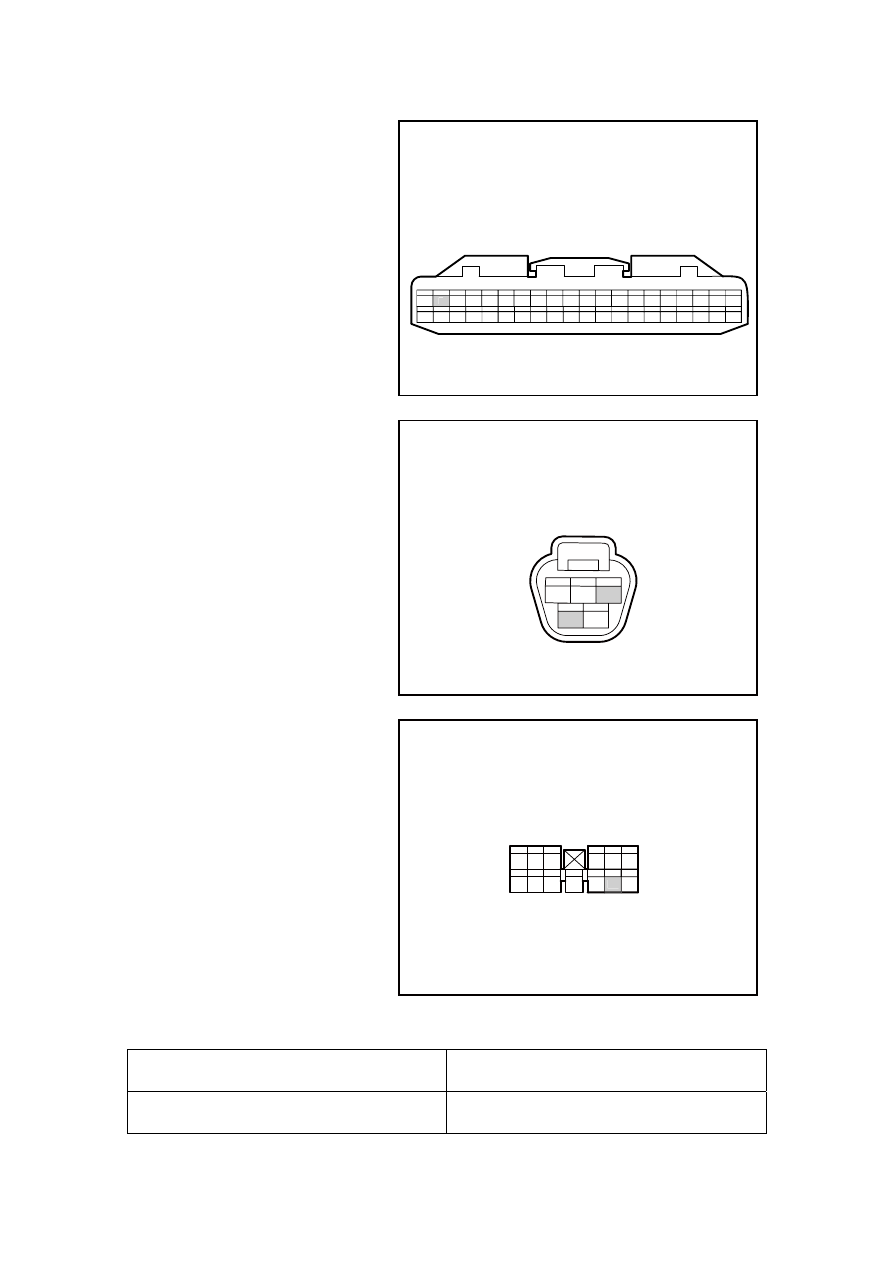
(f)  Measure harness energy guide 

between BCM harness connector 
terminal and wiper switch. Wiper 
motor by millimeter. 

NL11-2117b

IP50 车身控制模块线束连接器4

1

2

3

4

5

6

7

8

9 10 11 12 13 14 15 16 17 18 19 20

21 22 23 24 25 26 27 28 29 30 31 32 33 34 35 36 37 38 39 40

2


NL11-2105b

1

4

5

2

3

CA14 前雨刮器电机线束连接器


NL11-2108b

IP47 车身控制模块线束连接器2

1 2 3

4 5 6

7 8 9

10 11 12 13

12


Test terminal 

Specified value 

IP50(2)-IP52(7) Less 

than 

Ω 

IP50 body control module harness 

connector4 

CA14 front wiper motor harness 

connector 

IP47 body control module harness 

connector2 

2271

IP48(12)-CA14(2) Less 

than 

Ω 

Confirm whether the resistance conforms to standard value. 


Repair the wire harness fault point among the BCM wire harness connector terminal, the 
wiper switch and the wiper motor. 

(a)  Repair wire harness fault points between BCM wire harness connector terminal and wiper 

switch, wiper motor. 

(b)  Connect wiper switch wire harness connector IP52. 

(c)  Connect to BCM harness connector IP50, IP48. 

(d)  Connect to wiper harness connector CA14. 

(e)  Connect the battery negative cable. 

(f)  Turn on ignition switch to "ON" position. 

(g)  Operated wiper switch low speed (LOW). 

(h)  Voltage between wiper motor wire harness connector CA14 terminal No. 2 and vehicle body. 

Standard voltage: 11-14 V 

Confirm whether the voltage is normal. 


(a) Replace 

BCM. 

Confirm whether the wiper works normally. 


7 Replace 

wiper 

motor 

Replace wiper motor, refer to11.5.8.10 Replace wiper motor 

Confirm the completion of repair. 


Replace the BCM 

Next 

Yes 

The system is normal. 

No 

Yes 

Go to step 7 

No 

Yes 

Go to step 6 

No 

2272

The system is normal. 


2273


11.6.7.6 Wiper inoperation at intermittent 

Circuit diagram: 

See 11.6.7.3 wiper does not work under any gear position. 

Diagnostic steps: 

Inspect the voltage of the terminal No. 2 of the wiper motor wire harness connector 
CA14 and the effective body grounding point. 


(a) Disconnect wiper motor harness 

connector CA14. 

(b)  Place wiper switch to interval 

(INT) position. 

(c)  Rotated ignition switch to "ON" 

position. 

(d) Use  multimeter  to  measure 

effective grounding voltage 
between wire harness connector 
CA14 terminal No. 2 and vehicle 
body. 

Standard voltage: 11-14 V 

Confirm if the voltage conforms to 
standard value. 

NL11-2105b

1

4

5

2

3

CA14 前雨刮器电机线束连接器


Inspect the wiper switch. 


(a)  Rotated ignition switch to "OFF" 

position. 

(b) Disconnect wiper switch harness 

connector IP52. 

(c)  Place wiper switch to interval 

gear and use multimeter to 
measure the connection situation 
of switch. 

NL11-2118b

1

2

3

4 5 6

7

8

9

14 15 16 17 18

10 11

12 13

IP52 雨刮洗涤器组合开关线束连接器

13

15


No 

Go to step 7 

Yes 

CA14 frontWiper motor harness 

connector 

IP52wiper washer combination 

switchharness connector 

2274


содержание   ..   564  565  566  567  568  569 ..