содержание .. 431 432 433 434 435 ..
Geely Emgrand X7. Manual part - 434
7. Max.refrigerate
(MAX
A/C)
The controller is demanded for operating in the maximum refrigerating mode.
Rotate the mode knob to "MAX A/C", the control module will control by the following states:
–
Mode valve: Mode valve is in blowing face position
– A/C:
On
–
Inside and outside circulation: Inside circulation
–
Bleed door valve: full cooling mode
Notes:
When regulating the control mode knob to revolve from the position "Max A/C", electric
The A/C system performs the previous working condition.
8.3.3.2 Power A/C work principle
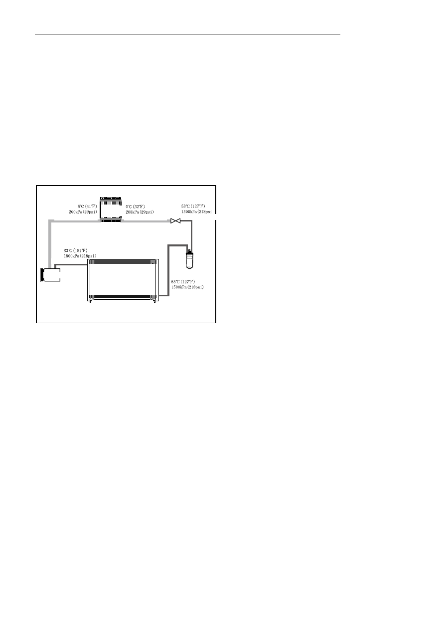
1. Refrigeration system work principle
NL08-2024b
The compressor is driven by the belt via the engine to extract the gaseous refrigerant from the evaporator and
compress it. The refrigerant is heated to 83°C to 110℃ at pressures up to 15 bar (1.47 MPa), and high-pressure
superheated refrigerant is conveyed to the condenser. At this time, heate in the refrigerant is carried away by the
air conveyed to the radiator fins, so the refrigerant is cooled down and is retained in the condenser due to the
dissipitation of such heat. Then, the refrigerant cooling to 53℃ and 70℃ is transmitted to the refrigerant storage
dryer under the high pressure. As an intermediate storage, the store fluid dry filters all moisture contained in the
refrigerant. The dry undercooling refrigerant is delivered to the entrance of the expansion value as a function of
the pressure and temperature in the evaporator; the expansion valve performs throttle and pressure reduction
control on the flow of the refrigerant entering into the evaporator, the pressure of the fog-like refrigerant from the
expansion valve is 2bar, the temperature is dropped to 0℃ to 2℃, and the fog-like refrigerant is heated to
evaporate in the evaporator. At last, the heat in the air is completely absorbed by the refrigerant in the evaporator
when entering the passenger compartment; therefore, when the air is cooled, the moisture mingled in the air is
condensed on the surface of the evaporator core. The low-pressure refrigerant air flow from the evaporator is
flowed to the upper opening of the expansion valve, the refrigerant pressure at this time is 2 bar and the
temperature is raised to 5℃ to 8℃. However, the compressor extracts the superheated refrigerant steam herein.
2. Heating
system
work
principle
Superheated vapor
Gas-liquid mixed mist
Evaporator
Supercooled liquid
Expansion valve
Superheated vapor
Compressor
Condenser
Fl
ui
d
reser
voi
r
dr
ye
r
Supercooled
liquid
Superheated vapor-saturated vapor-condensation-saturation
liquid-supercooled liquid
1735